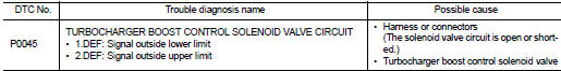
Nissan Juke Service and Repair Manual : P0045 TC boost control solenoid valve
DTC Logic
DTC DETECTION LOGIC
Diagnosis Procedure
1.CHECK TURBOCHARGER BOOST CONTROL SOLENOID VALVE POWER SUPPLY CIRCUIT
1. Turn ignition switch OFF.
2. Disconnect turbocharger boost control solenoid valve harness connector.
3. Turn ignition switch ON.
4. Check the voltage between turbocharger boost control solenoid valve harness connector and ground.
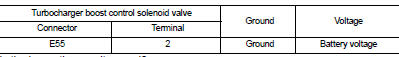
Is the inspection result normal? YES >> GO TO 3.
NO >> GO TO 2.
2.DETECT MALFUNCTIONING PART
Check the following.
• Harness for open or short between IPDM E/R and turbocharger boost control solenoid valve
>> Repair open circuit or short to ground or short to power in harness or connectors.
3.CHECK TURBOCHARGER BOOST CONTROL SOLENOID VALVE OUTPUT SIGNAL CIRCUIT FOR OPEN AND SHORT
1. Turn ignition switch OFF.
2. Disconnect ECM harness connector.
3. Check the continuity between turbocharger boost control solenoid valve harness connector and ECM harness connector.
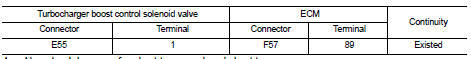
4. Also check harness for short to ground and short to power.
Is the inspection result normal? YES >> GO TO 4.
NO >> Repair open circuit or short to ground or short to power in harness or connectors.
4.CHECK TURBOCHARGER BOOST CONTROL SOLENOID VALVE
Refer to EC-894, "Component Inspection".
Is the inspection result normal? YES >> GO TO 5.
NO >> Replace turbocharger boost control solenoid valve.
5.CHECK INTERMITTENT INCIDENT
Refer to GI-42, "Intermittent Incident", ???INCIDENT SIMULATION TESTS??? and ???GROUND INSPECTION???.
>> INSPECTION END
Component Inspection
1.CHECK TURBOCHARGER BOOST CONTROL SOLENOID VALVE
1. Turn ignition switch OFF.
2. Disconnect turbocharger boost control solenoid valve harness connector.
3. Check resistance between turbocharger boost control solenoid valve terminals as follows.
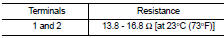
Is the inspection result normal? YES >> INSPECTION END
NO >> Replace turbocharger boost control solenoid valve.
 P0016 CKP - CMP correlation
DTC Logic
DTC DETECTION LOGIC
Diagnosis Procedure
1.CHECK CKP SENSOR AND CMP SENSOR
Refer to EC-932, "Diagnosis Procedure" (CKP sensor) and EC-934, "Diagnosis
Procedure" (C ...
 P0087 fuel pump
DTC Logic
DTC DETECTION LOGIC
NOTE:
• Conditions for applying the diagnostic procedure to the stored DTCs:
The DTC becomes present during the first 30 seconds after the engine starts.
• In ...
Other materials:
How to read the displayed lines
Guiding lines which indicate the vehicle width and distances to objects with
reference to the bumper lineA are displayed on the monitor.
Distance guide lines:
Indicate distances from the bumper.
• Red line1 : approx. 1.5 ft (0.5 m)
• Yellow line2 : approx. 3 ft (1 m)
• Green line3 : a ...
Precaution Necessary for Steering Wheel Rotation after Battery Disconnect
NOTE:
• Before removing and installing any control units, first turn the ignition
switch to the LOCK position, then disconnect
both battery cables.
• After finishing work, confirm that all control unit connectors are connected
properly, then re-connect both
battery cables.
• Always us ...
P060B ECM
DTC Logic
DTC DETECTION LOGIC
Diagnosis Procedure
1.INSPECTION START
1. Turn ignition switch ON.
2. Erase DTC.
3. Turn ignition switch OFF and wait for 20 seconds.
4. Turn ignition switch ON and perform the self-diagnosis.
Is the DTC P060B displayed again?
YES >> GO TO 2.
NO &g ...
