Nissan Juke Service and Repair Manual : Unit removal and installation
Engine assembly
Exploded View
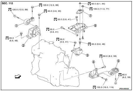
1. Engine torque rod
2. Engine mounting insulator
3. Engine mounting stay
4. Transaxle mounting stay
5. Engine mounting rear bracket
6. Transaxle torque rod
7. Transaxle mounting upper bracket
8. Transaxle mounting insulator
 : Vehicle front
 : N┬Ęm (kg-m, ft-lb)
Removal and Installation
WARNING:
ŌĆó Situate vehicle on a flat and solid surface.
ŌĆó Place chocks at front and back of rear wheels.
ŌĆó For engines not equipped with engine slingers, attach proper slingers and bolts described in PARTS CATALOG.
CAUTION:
ŌĆó Always be careful to work safely, avoid forceful or uninstructed operations.
ŌĆó Never start working until exhaust system and coolant are cool enough.
ŌĆó If items or work required are not covered by the engine main body section, refer to the applicable sections.
ŌĆó Always use the support point specified for lifting.
ŌĆó Use either 2-pole lift type or separate type lift as best you can. If board-on type is used for unavoidable reasons, support at the rear axle jacking point with transmission jack or similar tool before starting work, in preparation for the backward shift of center of gravity.
ŌĆó For supporting points for lifting and jacking point at rear axle, refer to GI-37, "Board-On Lift".
REMOVAL
Description of work
Remove engine and transaxle assembly from vehicle down ward. Separate engine and
transaxle.
Preparation
1. Remove the following parts.
ŌĆó Battery ground cable.
ŌĆó Engine undercover.
ŌĆó LH/RH front wheel. Refer to WT-7, "Exploded View".
ŌĆó LH/RH fender protector. Refer to EXT-22, "Exploded View".
Engine room
2. Drain engine coolant. Refer to CO-62, "Draining".
CAUTION:
Perform when engine is cold.
3. Remove air cleaner case. Refer to EM-280, "Exploded View".
4. Remove turbocharger air inlet pipe. Refer to EM-280, "Exploded View".
5. Remove reservoir tank hoses. Refer to CO-66, "Exploded View".
6. Remove radiator upper hose. Refer to CO-66, "Exploded View".
7. Remove cooling fan shroud assembly. Refer to CO-68, "Exploded View".
8. Remove alternator.
9. Remove vacuum hose. Refer to EM-293, "Exploded View".
10. Disconnect heater hoses.
11. Disconnect engine room harness from the engine side and set it aside for easier work.
12. Disconnect transaxle side harness and clutch tube.
13. Disconnect shift cable and select cable. Refer to TM-78, "Exploded View".
14. Disconnect all the body-side vacuum hoses and air hoses at engine side.
15. Disconnect fuel feed and return hoses, and plug it to prevent fuel from draining.
Vehicle underbody
16. Remove radiator lower hose. Refer to CO-66, "Exploded View".
17. Disconnect thermo plunger connector and earth cable. Refer to CO-72, "Exploded View".
18. Remove thermo plunger unit stay, and set thermo plunger unit aside for easier work.
19. Remove drive shaft lock pin and lock nut. Refer to FAX-77, "Exploded View".
20. Remove strut lower bolts.
21. Remove drive shaft assembly RH and LH. Refer to FAX-77, "Exploded View".
22. Remove A/C compressor with piping connected from engine. Temporarily secure it on body with a rope to avoid putting load on it.
23. Remove altarnator bracket.
24. Remove diesel particulate filter assembly. Refer to EX-17, "Exploded View".
25. Remove engine rear mounting bracket.
Removal
26. Use a manual lift table caddy (commercial service tool) or equivalently
rigid tool such as a jack or trestle. Securely support bottom
of engine and transaxle.
CAUTION:
Put a piece of wood or something similar as the supporting
surface, secure a completely stable condition.
27. Remove RH and LH engine mounting bolts.
28. Remove engine and transaxle assembly from vehicle downward by carefully operating supporting tools.
CAUTION:
ŌĆó During the operation, make sure that no part interferes
with body side.
ŌĆó Before and during this lifting, always check if any harnesses are left connected.
ŌĆó During the removal operation, always be careful to prevent vehicle from falling off the lift due to changes in the center of gravity.
ŌĆó If necessary, support vehicle by setting a jack or equivalent tool at the rear.
Separation Work
CAUTION:
During the operation, secure support the engine by placing a piece of wood under
the engine oil pan,
transaxle oil pan and suspended the engine slinger by baby crane (movable hoist)
etc.
29. Remove starter motor.
30. Separate engine and transaxle.
31. Lift with the hoist and separate the engine from the transaxle assembly.
INSTALLATION
Install in the reverse order of removal.
ŌĆó Do not allow oil to get on mounting insulator. Be careful not to damage mounting insulator.
ŌĆó When installation directions are specified, install parts according to the direction marks on them referring to components illustration.
ŌĆó Make sure that each mounting insulator is seated properly, and tighten mounting bolts and nuts.
Inspection
INSPECTION AFTER INSTALLATION
ŌĆó Before starting engine check the levels of coolant, lubrications and working oils. If less than required quantity, fill to the specified level.
ŌĆó Before starting engine, bleed air from fuel piping. Refer to FL-50, "Air Bleeding".
ŌĆó Run engine to check for unusual noise and vibration.
ŌĆó Warm up engine thoroughly to make sure there is no leakage of coolant, lubricants, working oil, fuel and exhaust gas.
ŌĆó Bleed air from passages in pipes and tubes of applicable lines.
 Cylinder head
Exploded View
1. Camshaft sprocket
2. Cylinder head suspended bracket
3. Valve lifter
4. Valve rotator
5. Valve spring retainer
6. Valve spring
7. Exhaust valve
8. Intake valve
9. Val ...

Other materials:
Excessive operation frequency
Description
ESP function, TCS function, ABS function, EBD function and brake limited slip
differential (BLSD) function
operates in excessive operation frequency.
Diagnosis Procedure
1.CHECK BRAKING FORCE
Check brake force using a brake tester.
Is the inspection result normal?
YES >> ...
Removal and installation
MULTI DISPLAY UNIT
Exploded View
REMOVAL
Refer to IP-12, "Exploded View".
DISASSEMBLY
1. Silencer tape
2. Multi display unit
3. Silencer tape
4. Clip
5. Control finisher
Removal and Installation
REMOVAL
Refer to IP-12, "Exploded View".
CAUTION:
ŌĆó When per ...
Brakes
If you notice that the braking system does not feel responsive or operate as expected, have the vehicle inspected immediately. We recommend visiting a NISSAN certified LEAF dealer for professional brake servicing.
WARNING
Never attempt to adjust the height of the brake pedal yourself. Tamp ...
