Nissan Juke Service and Repair Manual : Rear door lock
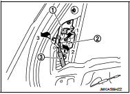
Exploded View
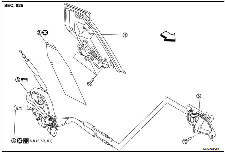
1. Outside handle assembly
2. Rear door sealing screen
3. Door lock assembly
4. TORX bolt
5. Inside handle
 : Clip
 : Pawl
 : Vehicle front
 : Do not reuse
 : N┬Ěm (kg-m, in-lb)
 : Body grease
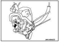
Door lock
DOOR LOCK : Removal and Installation
REMOVAL
1. Remove rear door glass and rear door lower sash (rear). Refer to GW-21, "Removal and Installation".
2. Remove inside handle. Refer to DLK-594, "INSIDE HANDLE : Removal and Installation".
3. Remove outside handle. Refer to DLK-594, "OUTSIDE HANDLE : Removal and Installation".
4. Remove door lock assembly TORX bolts.
5. Disconnect door lock actuator connector, and then remove door lock assembly.
INSTALLATION
Note the following items, and install in the reverse order of removal.
CAUTION:
ÔÇó Never reuse TORX bolt. Always replace it with a new one when it is removed.
ÔÇó Check door open/close, lock/unlock operation after installation.
ÔÇó Check door lock assembly for poor lubrication. Apply body grease to door lock if necessary.
 : Grease up point
Inside handle
INSIDE HANDLE : Removal and Installation
REMOVAL
1. Remove rear door finisher. Refer to INT-16, "Removal and Installation".
2. Remove upper side of sealing screen.
NOTE
:
Cut the butyl tape so that some parts of the butyl tape do not remain on the
sealing screen, if the sealing
screen is reused.
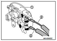
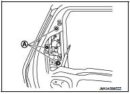
3. Remove inside handle mounting bolt (A).
4. Disengage inside handle (1) from door panel (2) while sliding inside handle toward vehicle rear, and then separate inside handle.
 : Vehicle front
5. Disengage inside handle cable (3) and lock knob cable (2), and then remove inside handle (1).
INSTALLATION
Note the following item, and install in the reverse order of removal.
CAUTION:
Check door open/close, lock/unlock operation after installation.
Outside handle
OUTSIDE HANDLE : Removal and Installation
REMOVAL
1. Remove rear door finisher and rear door corner cover inner. Refer to INT-16, "Removal and Installation".
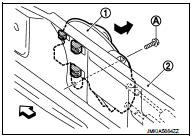
2. Remove rear door sealing screen.
3. Rotate stopper (1) upward.
4. Disengage outside handle cable (2), and then remove outside handle cable from outside handle assembly (3).
5. Remove outside handle assembly mounting bolts (A).
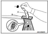
6. Disengage mounting clips using a remover tool (A), and then remove outside handle assembly.
CAUTION:
Apply protective tape (B) on the door panel to protect the
painted surface from damage.
 : Clip
INSTALLATION
Note the following items, and install in the reverse order of removal.
CAUTION:
ÔÇó Never reuse rear door sealing screen. Always replace it with a new one when it
is removed. When installing rear door sealing screen, install it according to
the following procedure.
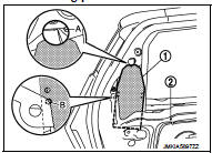
- Put lower portion of rear door sealing screen (1) into inside of door panel (2).
- Perform positioning according to the following procedure, and then install rear door sealing screen.
ÔÇó Align upper portion of rear door sealing screen to hole (A) of door panel as shown in the figure.
ÔÇó Align hole of rear door sealing screen to edge (B) of door panel as shown in the figure.
ÔÇó Be careful to position outside handle cable normally when installing it. For details, refer to DLK-593, "Exploded View".
ÔÇó Check door open/close, lock/unlock operation after installation.
 Front door lock
Exploded View
1. Door key cylinder assembly (driver
side)
Outside handle escutcheon (passenger
side)
2. Rear gasket
3. Outside handle bracket
4. TORX bolt
5. Key rod (driver side)
6. Doo ...
 Back door lock
Exploded View
1. Back door lock assembly
2. TORX bolt
3. Back door striker
: Do not reuse
: N┬Ěm (kg-m, ft-lb)
: Body grease
Door lock
DOOR LOCK : Removal and Installation
REMOVAL
1. Rem ...
Other materials:
Air breather hose
Removal and Installation
REMOVAL
1. Remove clip from bracket.
2. Remove air breather hose from transaxle assembly.
INSTALLATION
Note the following, and install in the reverse order of removal.
CAUTION:
ÔÇó Check that air breather hose is not collapsed or blocked due to folding or
bendin ...
Loss of power
Description
CHART 12: LOSS OF POWER
Diagnosis Procedure
1.CHECK FUEL
Check that the fuel reservoir is correctly filled and with the right fuel.
>> GO TO 2.
2.CHECK FUEL FILTER
Check the correctness of the fuel filter.
Is the fuel filter correct?
Yes >> GO TO 3.
No >& ...
Intelligent key warning buzzer
Component Function Check
1.CHECK FUNCTION
1. Select ÔÇťINTELLIGENT KEYÔÇŁ of ÔÇťBCMÔÇŁ using CONSULT-III.
2. Select ÔÇťOUTSIDE BUZZERÔÇŁ in ÔÇťACTIVE TESTÔÇŁ mode.
3. Check that the function operates normally according to the following
conditions.
Is the inspection result normal?
YES >& ...
