Nissan Juke Service and Repair Manual : Intelligent key warning buzzer
Component Function Check
1.CHECK FUNCTION
1. Select ÔÇťINTELLIGENT KEYÔÇŁ of ÔÇťBCMÔÇŁ using CONSULT-III.
2. Select ÔÇťOUTSIDE BUZZERÔÇŁ in ÔÇťACTIVE TESTÔÇŁ mode.
3. Check that the function operates normally according to the following conditions.
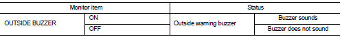
Is the inspection result normal? YES >> Intelligent Key warning buzzer is OK.
NO >> Refer to DLK-263, "Diagnosis Procedure".
Diagnosis Procedure
1.CHECK FUSE
1. Turn ignition switch OFF.
2. Check 10 A fuse, [No. 7, located in fuse block (J/B)].
Is the inspection result normal? YES >> GO TO 2.
NO >> Replace the blown fuse after repairing the affected circuit if a fuse is blown.
2.CHECK INTELLIGENT KEY WARNING BUZZER POWER SUPPLY CIRCUIT
1. Disconnect Intelligent Key warning buzzer connector.
2. Check voltage between Intelligent Key warning buzzer harness connector and ground.
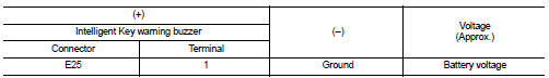
Is the inspection result normal? YES >> GO TO 3.
NO >> Repair or replace harness.
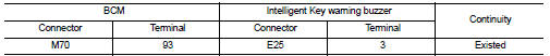
3.CHECK INTELLIGENT KEY WARNING BUZZER CIRCUIT
1. Disconnect BCM connector.
2. Check continuity between BCM harness connector and Intelligent Key warning buzzer harness connector.
3. Check continuity between BCM harness connector and ground.
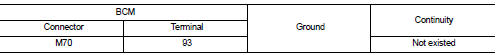
Is the inspection result normal? YES >> GO TO 4.
NO >> Repair or replace harness.
4.CHECK INTELLIGENT KEY WARNING BUZZER
Refer to DLK-264, "Component Inspection".
Is the inspection result normal? YES >> Replace BCM. Refer to BCS-93, "Removal and Installation".
NO >> Replace Intelligent Key warning buzzer.
Component Inspection
1.CHECK INTELLIGENT KEY WARNING BUZZER
1. Turn ignition switch OFF.
2. Disconnect Intelligent Key warning buzzer connector.
3. Connect battery power supply directly to Intelligent Key warning buzzer terminals and check the operation.
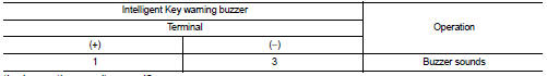
Is the inspection result normal? YES >> INSPECTION END
NO >> Replace Intelligent Key warning buzzer.
 Intelligent key
Component Function Check
1.CHECK FUNCTION
1. Select ÔÇťINTELLIGENT KEYÔÇŁ of ÔÇťBCMÔÇŁ using CONSULT-III.
2. Select ÔÇťRKE OPE COUN1ÔÇŁ in ÔÇťDATA MONITORÔÇŁ mode.
3. Check that the function opera ...
 Key warning lamp
Component Function Check
1.CHECK FUNCTION
1. Select ÔÇťINTELLIGENT KEYÔÇŁ of ÔÇťBCMÔÇŁ using CONSULT-III.
2. Select ÔÇťINDICATORÔÇŁ in ÔÇťACTIVE TESTÔÇŁ mode.
3. Check that the function operates n ...
Other materials:
Precaution for Supplemental Restraint System (SRS) "AIR BAG" and "SEAT BELT
PRE-TENSIONER"
The Supplemental Restraint System such as ÔÇťAIR BAGÔÇŁ and ÔÇťSEAT BELT PRE-TENSIONERÔÇŁ,
used along
with a front seat belt, helps to reduce the risk or severity of injury to the
driver and front passenger for certain
types of collision. Information necessary to service the system safely is
...
Blower motor
Diagnosis Procedure
1.CHECK SYMPTOM
Check symptom (A or B).
Which symptom is detected?
A >>GO TO 2.
B >>GO TO 7.
2.CHECK FUSE
1. Turn ignition switch OFF.
2. Check 15A fuses (Nos. 14 and 16, located in fuse block (J/B)].
NOTE:
Refer to PG-22, "Fuse, Connector and T ...
Component parts
INTERIOR LIGHTING SYSTEM
INTERIOR LIGHTING SYSTEM : Component Parts Location
1. IPDM E/R
Refer to PCS-5, "Component Parts
Location"
2. BCM
Refer to BCS-6, "BODY CONTROL
SYSTEM : Component Parts Location"
3. Door lock and unlock switch
4. Front door request switch (driv ...
