Nissan Juke Service and Repair Manual : Front door lock
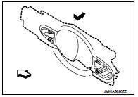
Exploded View
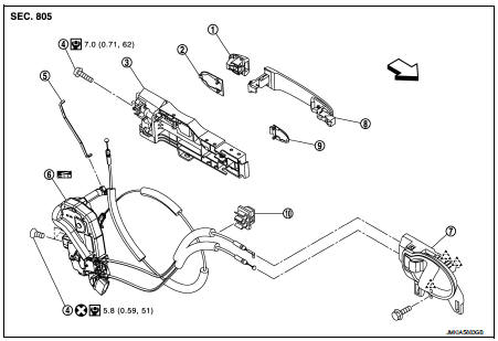
1. Door key cylinder assembly (driver
side)
Outside handle escutcheon (passenger
side)
2. Rear gasket
3. Outside handle bracket
4. TORX bolt
5. Key rod (driver side)
6. Door lock assembly
7. Inside handle
8. Outside handle
9. Front gasket
10. Cable clip
 : Pawl
 : Vehicle front
 : Do not reuse
 : N┬Ęm (kg-m, in-lb)
 : Body grease
Door lock
DOOR LOCK : Removal and Installation
REMOVAL
1. Remove front door glass and front door lower sash (rear). Refer to GW-17, "Removal and Installation".
2. Remove inside handle. Refer to DLK-590, "INSIDE HANDLE : Removal and Installation".
3. Disengage inside handle cable and lock knob cable from cable clip.
4. Remove outside handle bracket. Refer to DLK-590, "OUTSIDE HANDLE : Removal and Installation".
5. Remove door lock assembly TORX bolts.
6. Disconnect door lock actuator connector, and then remove door lock assembly.
INSTALLATION
Note the following items, and install in the reverse order of removal.
CAUTION:
ŌĆó Never reuse TORX bolt. Always replace it with a new one when it is removed.
ŌĆó Check door open/close, lock/unlock operation after installation.
ŌĆó Check door lock cable is properly engaged with outside handle bracket.
ŌĆó Check door lock assembly for poor lubrication. Apply body grease to door lock if necessary.
 : Grease up point

Inside handle
INSIDE HANDLE : Removal and Installation
REMOVAL
1. Remove front door finisher. Refer to INT-13, "Removal and Installation".
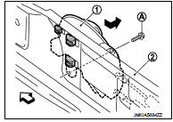
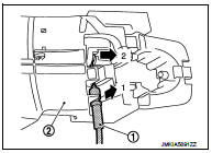
2. Remove inside handle mounting bolt (A).
3. Disengage inside handle (1) from door panel (2) while sliding inside handle toward vehicle rear, and then separate inside handle.
 : Vehicle front
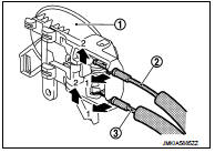
4. Disengage inside handle cable (3) and lock knob cable (2), and then remove inside handle (1).
INSTALLATION
Note the following item, and install in the reverse order of removal.
CAUTION:
Check door open/close, lock/unlock operation after installation.
Outside handle
OUTSIDE HANDLE : Removal and Installation
REMOVAL
1. Fully close the front door glass.
2. Remove front door finisher. Refer to INT-13, "Removal and Installation".
3. Remove sealing screen.
NOTE
:
Cut the butyl-tape so that some parts of the butyl-tape do not remain on the
sealing screen, if the sealing
screen is reused.
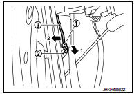
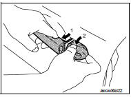
4. Disengage lock holder (1), and then separate key rod (3) from door lock assembly (2).(Driver side)
5. Remove grommet (1) of door side. Loosen, through grommet hole, TORX bolt (2) that fixes door lock cylinder. (For passenger side, TORX bolt fixes outside handle escutcheon.)
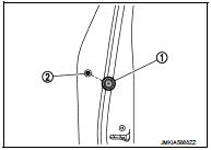
6. While pulling outside handle, remove door key cylinder assembly (diver side) or outside handle escutcheon (passenger side).
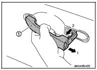
7. While pulling outside handle (1), slide toward rear of vehicle to remove outside handle.
8. Remove front gasket (1) and rear gasket (2).
 : Vehicle front
9. Slide outside handle bracket toward rear of vehicle to remove.
 : Vehicle front
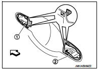
10. Disconnect outside handle cable (1) from outside handle bracket (2).
INSTALLATION
Note the following items, and install in the reverse order of removal.
CAUTION:
ŌĆó When installing key rod, rotate key rod holder until a click is felt.
ŌĆó Check that door lock cables are normally engaged with inside handle and outside handle.
ŌĆó After installation, check door open/close, and lock/unlock operation.
 Hood lock
Exploded View
1. Hood lock control cable assembly
2. Hood lock assembly
: Clip
: N┬Ęm (kg-m, ft-lb)
: Body grease
Hood lock
HOOD LOCK : Removal and Installation
REMOVAL
1. Remove front cen ...
 Rear door lock
Exploded View
1. Outside handle assembly
2. Rear door sealing screen
3. Door lock assembly
4. TORX bolt
5. Inside handle
: Clip
: Pawl
: Vehicle front
: Do not reuse
: N┬Ęm (kg-m, in-lb ...
Other materials:
Emission control system warranty
Your NISSAN is covered by the following emission warranties.
For USA:
ŌĆó Emission Defects Warranty
ŌĆó Emissions Performance Warranty
Details of these warranties may be found with other vehicle warranties in your
Warranty Information Booklet which comes with your NISSAN. If you di ...
P061A ECM
DTC Logic
DTC DETECTION LOGIC
Diagnosis Procedure
1.INSPECTION START
1. Turn ignition switch ON.
2. Erase DTC.
3. Turn ignition switch OFF and wait for 20 seconds.
4. Turn ignition switch ON and perform the self-diagnosis.
Is the DTC P061A displayed again?
YES >> GO TO 2.
NO &g ...
Air cleaner
To remove the filter, pull the air duct1 upward to remove it. Pull the tabs 2
, then pull the cover3 upward.
The air cleaner filter should not be cleaned and reused. Replace it according
to the maintenance shown in the ŌĆ£NISSAN Service and Maintenance GuideŌĆØ. When replacing
the filter, w ...
