Nissan Juke Service and Repair Manual : Upper link
Exploded View
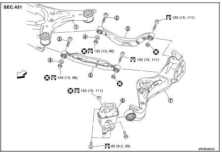
1. Rear suspension member
2. Adjusting bolt
3. Upper link
4. Eccentric disk
5. Lower link
6. Suspension arm bracket
7. Suspension arm
 : Vehicle front
 : Always replace after every
disassembly.
 : N┬Ęm (kg-m, ft-lb)
Removal and Installation
REMOVAL
1. Remove tires. WT-7, "Removal and Installation".
2. Remove wheel sensor and sensor harness. Refer to BRC-86, "REAR WHEEL SENSOR : Removal and Installation" (Without ESP), BRC-227, "REAR WHEEL SENSOR : Removal and Installation" (With ESP).
3. Set jack under suspension arm.
CAUTION:
ŌĆó Never damage the suspension arm with a jack.
ŌĆó Check the stable condition when using a jack.
4. Remove eccentric disc, adjusting bolt, mounting bolt, and nut, then remove upper link.
5. Perform inspection after removal. Refer to RSU-33, "Inspection".
INSTALLATION
Note the following, and install in the reverse order of removal.
ŌĆó Perform final tightening of rear suspension member and axle installation position (rubber bushing), under unladen conditions with tires on level ground.
ŌĆó Never reuse upper link mounting nut.
ŌĆó Perform inspection after installation. Refer to RSU-33, "Inspection".
Inspection
INSPECTION AFTER REMOVAL
Check upper link and bushing for any deformation, cracks, or damage. Replace it if necessary.
INSPECTION AFTER INSTALLATION
1. Check wheel sensor harness for proper connection. Refer toBRC-85, "REAR WHEEL SENSOR : Exploded View" (Without ESP), BRC-225, "REAR WHEEL SENSOR : Exploded View" (With ESP).
2. Check wheel alignment. Refer to RSU-20, "Inspection".
3. Adjust neutral position of steering angle sensor. Refer to BRC-149, "Work Procedure" (With ESP).
 Lower link
Exploded View
1. Rear suspension member
2. Adjusting bolt
3. Upper link
4. Eccentric disk
5. Lower link
6. Suspension arm bracket
7. Suspension arm
: Vehicle front
: Always replace afte ...
 Rear stabilizer
Exploded View
1. Stabilizer bar
2. Bushing
3. Stabilizer clamp
4. Stabilizer link
5. Lower link
6. Rear suspension member
: Vehicle front
: Always replace after every
disassembly.
: N ...
Other materials:
Service Notice or Precautions for Clut
WARNING:
After cleaning clutch disc, wipe it with a dust collector. Never use compressed
air.
CAUTION:
ŌĆó Clutch fluid use refer to MA-13, "Fluids and Lubricants".
ŌĆó Never reuse drained clutch fluid.
ŌĆó Keep painted surface on the body or other parts free of clutch fluid. If i ...
P0171 fuel injection system function
DTC Logic
DTC DETECTION LOGIC
With the Air/Fuel Mixture Ratio Self-Learning Control, the actual mixture
ratio can be brought closely to the
theoretical mixture ratio based on the mixture ratio feedback signal from the
A/F sensors 1. The ECM calculates
the necessary compensation to correct th ...
Service Equipment
RECOVERY/RECYCLING RECHARGING EQUIPMENT
Be certain to follow the manufacturerŌĆÖs instructions for machine operation
and machine maintenance. Never
introduce any refrigerant other than that specified into the machine.
ELECTRICAL LEAK DETECTOR
Be certain to follow the manufacturerŌĆÖs instruc ...
