Nissan Juke Service and Repair Manual : Rear stabilizer
Exploded View
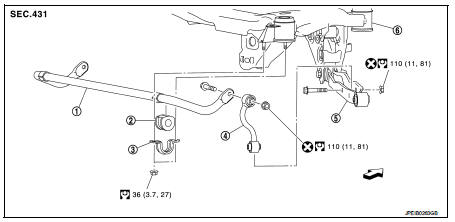
1. Stabilizer bar
2. Bushing
3. Stabilizer clamp
4. Stabilizer link
5. Lower link
6. Rear suspension member
 : Vehicle front
 : Always replace after every
disassembly.
 : N·m (kg-m, ft-lb)
Removal and Installation
REMOVAL
1. Remove stabilizer link.
2. Remove center pipe. Refer to EX-6, "Removal and Installation".
3. Remove mounting nuts on stabilizer clamp, bushing, and stabilizer bar from suspension member.
4. Perform inspection after removal. Refer to RSU-34, "Inspection".
INSTALLATION
Note the following, and install in the reverse order of removal.
• Perform final tightening of rear suspension member and axle installation position (rubber bushing), under unladen conditions with tires on level ground.
• Never reuse stabilizer link mounting nut.
Inspection
INSPECTION AFTER REMOVAL
Check stabilizer bar, stabilizer link, stabilizer bushing and stabilizer clamp for deformation, cracks or damage.
Replace it if necessary.
 Upper link
Exploded View
1. Rear suspension member
2. Adjusting bolt
3. Upper link
4. Eccentric disk
5. Lower link
6. Suspension arm bracket
7. Suspension arm
: Vehicle front
: Always replace afte ...
 Rear suspension assembly
Exploded View
1. Rear suspension member
2. Rebound stopper
3. Washer
: Vehicle front
N·m (kg-m, ft-lb)
Removal and Installation
REMOVAL
1. Remove tires. Refer to WT-7, "Removal and ...
Other materials:
B1134 side air bag module LH
DTC Logic
DTC DETECTION LOGIC
DTC CONFIRMATION PROCEDURE
1.CHECK SELF-DIAG RESULT
With CONSULT-III
1. Turn ignition switch ON.
2. Perform “Self Diagnostic Result” mode of “AIR BAG” using CONSULT-III.
Without CONSULT-III
1. Turn ignition switch ON.
2. Check the air bag warning la ...
Replacement operations
Description
• This section is prepared for technicians who have attained a high level of
skill and experience in repairing
collision-damaged vehicles and also use modern service tools and equipment.
Persons unfamiliar with body
repair techniques should not attempt to repair collision-damage ...
Precaution
Precaution for Supplemental Restraint System (SRS) "AIR BAG" and "SEAT
BELT
PRE-TENSIONER"
The Supplemental Restraint System such as “AIR BAG” and “SEAT BELT PRE-TENSIONER”,
used along
with a front seat belt, helps to reduce the risk or severity of injury to the
...
