Nissan Juke Service and Repair Manual : Lower link
Exploded View
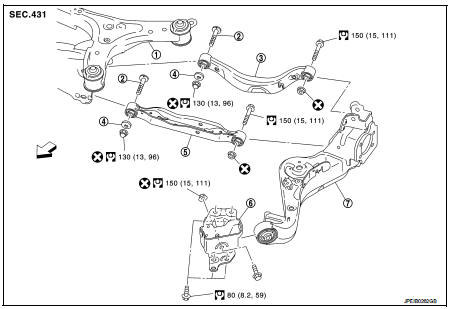
1. Rear suspension member
2. Adjusting bolt
3. Upper link
4. Eccentric disk
5. Lower link
6. Suspension arm bracket
7. Suspension arm
 : Vehicle front
 : Always replace after every
disassembly.
 : N·m (kg-m, ft-lb)
Removal and Installation
REMOVAL
1. Remove tires. Refer to WT-7, "Removal and Installation".
2. Set jack under suspension arm.
CAUTION:
• Never damage the suspension arm with a jack.
• Check the stable condition when using a jack
.
3. Remove stabilizer link. Refer to RSU-34, "Removal and Installation".
4. Remove eccentric disc, adjusting bolt, mounting bolt, and nut, then remove lower link.
5. Perform inspection after removal. Refer to RSU-31, "Inspection".
INSTALLATION
Note the following, and install in the reverse order of removal.
• Perform final tightening of rear suspension member and axle installation position (rubber bushing), under unladen conditions with tires on level ground.
• Never reuse lower link mounting nut.
• Perform inspection after installation. Refer to RSU-31, "Inspection".
Inspection
INSPECTION AFTER REMOVAL
Check lower link and bushing for any deformation, cracks, or damage. Replace it if necessary.
INSPECTION AFTER INSTALLATION
1. Check wheel alignment. Refer to RSU-20, "Inspection".
2. Adjust neutral position of steering angle sensor. Refer to BRC-149, "Work Procedure" (With ESP).
 Suspension arm
Exploded View
1. Rear suspension member
2. Adjusting bolt
3. Upper link
4. Eccentric disk
5. Lower link
6. Suspension arm bracket
7. Suspension arm
: Vehicle front
: Always replace afte ...
 Upper link
Exploded View
1. Rear suspension member
2. Adjusting bolt
3. Upper link
4. Eccentric disk
5. Lower link
6. Suspension arm bracket
7. Suspension arm
: Vehicle front
: Always replace afte ...
Other materials:
Engine oil
Inspection
OIL LEVEL AND MUDDINESS
• Before starting the engine, check the oil level placing vehicle
horizontally.
If the engine is already started, stop it and allow 10 minutes
before checking.
• Make sure the oil level is within the range shown in the figure.
• If it is out of rang ...
Front suspension assembly
Inspection
COMPONENT PART
Check the mounting conditions (looseness, backlash) of each component and
component conditions (wear,
damage) are normal.
BALL JOINT AXIAL END PLAY
1. Set front wheels in a straight-ahead position.
2. Measure axial end play by prying it up/down with iron bar or eq ...
Information display (speed limiter)
Component Function Check
1.CHECK INFORMATION DISPLAY (SPEED LIMITER) FUNCTION
1. Start engine.
2. Press speed limiter MAIN switch.
3. Drive the vehicle at more than 30 km/h (20 MPH).
CAUTION:
Always drive vehicle at a safe speed.
4. Press SET/− switch.
5. Perform a test drive on a fl ...
