Nissan Juke Service and Repair Manual : Parking brake control
Exploded View
2WD
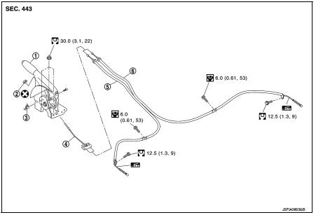
1. Parking brake lever assembly
2. Adjusting nut
3. Parking brake switch
4. Front cable
5. Rear cable (LH)
6. Rear cable (RH)
 : Apply multi-purpose grease.
 : N┬Ęm (kg-m, ft-lb)
 : N┬Ęm (kg-m, in-lb)
 : Always replace after every
disassembly.
4WD
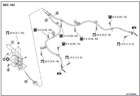
1. Parking brake lever assembly
2. Adjusting nut
3. Parking brake switch
4. Front cable
5. Rear cable (LH)
6. Rear cable (RH)
: Apply multi-purpose grease.
: N┬Ęm (kg-m, ft-lb)
: N┬Ęm (kg-m, in-lb)
: Always replace after every
disassembly.
Removal and Installation
REMOVAL
1. Remove rear tires.
2. Remove the center console assembly. Refer to IP-23, "Removal and Installation".
3. Disconnect the parking brake switch harness connector.
4. Remove adjusting nut (1) and loosen front cable.
5. Remove the parking brake lever assembly.
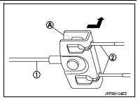
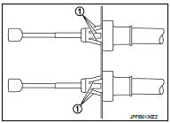
6. Remove rear cable with the following procedure.
a. Pull equalizer (A) of the front cable (1) in a rearward direction.
b. Push the equalizer upward to remove the rear cable (2).
7. Remove center muffler and heat plate.
ŌĆó MR16DDT: Refer to EX-6, "Removal and Installation".
ŌĆó HR16DE: Refer to EX-12, "Removal and Installation".
ŌĆó K9K: Refer to EX-17, "Removal and Installation".
8. Remove brake shoe, and remove rear cable from toggle lever.
Refer to PB-7, "Exploded View".
9. Remove rear cable mounting bolts, pull out rear cable from vehicle.
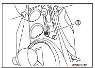
10. Press the pawl (1) to remove the rear cable from the vehicle.
INSTALLATION
Note the following, install in the reverse order of the removal.
ŌĆó Never reuse adjusting nut.
ŌĆó Perform adjustment after installation. Refer to PB-2, "Inspection and Adjustment".
Adjustment
ADJUSTMENT AFTER INSTALLATION
Adjust the parking brake lever stroke. Refer to PB-2, "Inspection and Adjustment".

 Parking brake shoe
Exploded View
1. Anti-rattle pin
2. Back plate
3. Toggle lever
4. Parking brake shoe
5. Brake strut
6. Return spring
7. Spring
8. Adjuster
: Apply PBC (Poly Butyl
Cuprysil) grease or ...
Other materials:
Basic inspection
Diagnosis and repair work flow
Work Flow
DETAILED FLOW
1.INTERVIEW FROM THE CUSTOMER
Clarify customer complaints before inspection. First of all, perform an
interview utilizing BRC-34, "Diagnostic
Work Sheet" and reproduce the symptom as well as fully understand it. Ask
customer a ...
ACC warning does not operate
Diagnosis Procedure
1.CHECK COMBINATION METER BUZZER
Check combination meter buzzer.
Refer to WCS-40, "Component Function Check".
Is the inspection result normal?
YES >> GO TO 2.
NO >> Repair or replace the malfunctioning parts.
2.REPLACE BCM
1. Replace BCM. Ref ...
Diagnosis system (IPDM E/R) (without intelligent key system)
Diagnosis Description
AUTO ACTIVE TEST
Description
In auto active test mode, the IPDM E/R sends a drive signal to the following
systems to check their operation.
ŌĆó Oil pressure warning lamp (only for K9K engine models)
ŌĆó Rear window defogger
ŌĆó Front wiper motor
ŌĆó Parking lamp
ŌĆó ...
