Nissan Juke Service and Repair Manual : High pressure supply pump
Exploded View
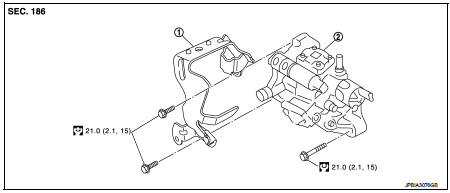
1. High pressure supply pump protector 2. High pressure supply pump
 : N┬Ęm (kg-m, ft-lb)
Removal and Installation
REMOVAL
CAUTION:
ŌĆó Be sure to read ŌĆ£Precautions for Diesel EquipmentŌĆØ. Refer to EM-263,
"Precaution for Diesel Equipment".
ŌĆó Wait until the fuel temperature drops before carrying out any work.
ŌĆó Order the special high pressure injection circuit plug kit.
ŌĆó In case of the replacement of the high pressure supply pump sprocket, please apply the following tightening torque:
 : 70.0 N┬Ęm (7.1 kg-m, 52 ft-lb)
1. Disconnect the battery cable from the negative terminal.
2. Remove cowl top extension. Refer to EXT-20, "Exploded View".
3. Remove turbocharger air inlet pipe. Refer to EM-280, "Exploded View".
4. Remove air inlet tube assembly and air inlet tube. Refer to EM-281, "Exploded View".
5. Remove the timing belt. Refer to EM-302, "Exploded View".
6. Remove the neck located on the fuel rail, 7. Remove the oil level gauge guide and plug the hole.
8. Remove high pressure protection cover. Refer to EM-294, "Exploded View".
9. Carefully disconnect:
ŌĆó The connectors from the flow actuator, ŌĆó The connectors from the fuel temperature sensor, ŌĆó On the pump, the fuel supply and return pipes.
ŌĆó The return pipe connecting the injectors with the pump.
10. Remove the injection tube connecting the pump to the rail. Refer to EM-294, "Exploded View".
11. Plug all the holes of the injection circuit.
12. Remove the three mounting bolts from the high pressure supply pump then remove it.
INSTALLATION
1. Install the pump then position the mounting bolts without tightening them.
2. Before fitting the new injection tube, lightly lubricate the nut threads with the oil from the sachet provided in the new parts kit.
3. Refit the injection tube, to do this:
ŌĆó remove the protective plugs,
ŌĆó insert the injection tube olive into the taper of the high pressure pump
outlet,
ŌĆó insert the injection tube olive into the taper of the high pressure rail
inlet.
4. Finger tighten the nuts of the injection tube starting with the one located on the rail side.
5. Tighten the mounting bolts on the high pressure pump.
: 21.0 N┬Ęm (2.1 kg-m, 15 ft-lb)
6. Tighten the injection tube nut.
: 24.0 N┬Ęm (2.4 kg-m, 18 ft-lb)
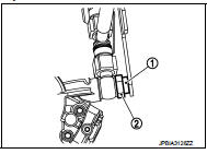
7. Refit high pressure supply pump protector.
CAUTION:
When refitting high pressure supply pump protector, follow steps below.
ŌĆó Be sure disk rubber (1) is touching bolt head of high pressure supply pump (2) as shown in the figure.
ŌĆó Tighten bolt with holding protector towards to high pressure supply pump.
:21.0 N┬Ęm (2.1 kg-m, 15 ft-lb)
ŌĆó Make sure disk rubber (1) is touching with bolt head of high pressure supply pump (2).
8. Refit in the reverse order to removal for the other refitting operations.
9. Test the sealing of the high pressure after it has been repaired (refer to ŌĆ£SPECIAL FEATURESŌĆØ in EM- 263, "Precaution for Diesel Equipment").
 5TH injector
Exploded View
1. 5th injector retaining bracket
2. 5th injector bolt
3. 5th injector
4. Injector seal
5. Diesel injector cooler
6. Gasket
7. Turbocharger outlet duct
: N┬Ęm (kg-m, ft-lb) ...
 Rocker cover
Exploded View
1. Blow-by hose
2. Rocker cover
3. Gasket
4. Camshaft position sensor
5. O-ring
A. To turbocharger air inlet pipe
: N┬Ęm (kg-m, in-lb)
: Always replace after every
disasse ...
Other materials:
Key interlock cable
Exploded View
1. CVT shift selector assembly
2. Key interlock cable
A: Key cylinder
B: Clip
C: Clip
Removal and Installation
REMOVAL
CAUTION:
Always apply the parking brake before performing removal and installation.
1. Shift the selector lever to the ŌĆ£PŌĆØ position.
2. Remove the ...
LAN System can system (type 11)
DTC/CIRCUIT DIAGNOSIS
Main line between IPDM-E and DLC circuit
Diagnosis Procedure
1.CHECK CONNECTOR
1. Turn the ignition switch OFF.
2. Disconnect the battery cable from the negative terminal.
3. Check the following terminals and connectors for damage, bend and loose
connection (connector s ...
P0075 IVT control solenoid valve
DTC Logic
DTC DETECTION LOGIC
DTC CONFIRMATION PROCEDURE
1.PRECONDITIONING
If DTC Confirmation Procedure has been previously conducted, always turn
ignition switch OFF and wait at
least 10 seconds before conducting the next test.
>> GO TO2.
2.PERFORM DTC CONFIRMATION PROCEDURE
...
