Nissan Juke Service and Repair Manual : 5TH injector
Exploded View
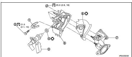
1. 5th injector retaining bracket
2. 5th injector bolt
3. 5th injector
4. Injector seal
5. Diesel injector cooler
6. Gasket
7. Turbocharger outlet duct
 : N·m (kg-m, ft-lb)
 : Always replace after every
disassembly.
Removal and Installation
REMOVAL
CAUTION:
• Be sure to read "Precautions for diesel equipment". Refer to EM-263,
"Precaution for Diesel Equipment".
• Make preparations for coolant outflow.
1. Remove air cleaner case. Refer to EM-280, "Exploded View".
2. Disconnect quick connector(1) and harness connector (2).
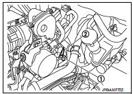
CAUTION:
• Be careful not to damage the connector.
• Be sure to read "Precautions for diesel equipment". Refer to EM-263, "Precaution for Diesel Equipment"
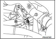
3. Remove the following parts from the upper side of the engine.
• Remove fixing bolt (A) of 5th injector retaining bracket (1) • Remove 5th injector retaining bracket (1).
4. Remove the 5th injector (2) and injector seal. Refer to EM-296, "Exploded View"
INSTALLATION
1. Clean the 5th injector: • Immerse the 5th injector in a container of diesel.
• Wipe using clean cloth.
CAUTION:
Never clean the 5th injector with:
• A wire brush,
• An emery cloth,
• An ultrasonic cleaner.
2. Always replace the injector seal.
3. Install the 5th injector, injector seal and 5th injector retaining bracket assembly.
CAUTION:
Before tightening the 5th injector retaining bracket, check that the 5th
injector is correctly positioned
in relation to the bracket.
4. Install the other parts in the reverse order of the removal.
 Injection tube and fuel injector
Exploded View
1. Spill hose
2. Injection tube
3. Fuel injector
4. Heat protection washer
5. Fuel injector bracket
6. Fuel injector bracket spacer
7. Fuel rail stud bolt
8. Fuel rail
9 ...
 High pressure supply pump
Exploded View
1. High pressure supply pump protector
2. High pressure supply pump
: N·m (kg-m, ft-lb)
Removal and Installation
REMOVAL
CAUTION:
• Be sure to read “Precautions for Diesel ...
Other materials:
Front fog lamp circuit
Component Function Check
1.CHECK FRONT FOG LAMP OPERATION
CONSULT-III ACTIVE TEST
1. Select “EXTERNAL LAMPS” of IPDM E/R active test item.
2. With operating the test items, check that the front fog lamp is turned ON.
Fog : Front fog lamp ON
Off : Front fog lamp OFF
Is the measurement norm ...
Camshaft
Exploded View
1. Camshaft position sensor (PHASE)
2. O-ring
3. Camshaft bracket
4. Camshaft (EXH)
5. Camshaft sprocket (EXH)
6. Camshaft sprocket (INT)
7. Camshaft (INT)
8. Valve lifter (EXH)
9. Valve lifter (INT)
10. Signal plate (INT)
11 Signal plate (EXH)
A.Tightening must be ...
License plate lamp circuit
Without daytime running light system
WITHOUT DAYTIME RUNNING LIGHT SYSTEM : Component Function Check
1.CHECK TAIL LAMP (RH) OPERATION
Check that the tail lamp (RH) is turned ON.
Is the inspection result normal?
YES >> GO TO 2.
NO >> Check tail lamp circuit. Refer to EXL-61, &qu ...
