Nissan Juke Service and Repair Manual : B257B, B257C ambient sensor
DTC Logic
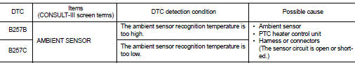
DTC DETECTION LOGIC
NOTE
:
• If DTC is displayed along with DTC U1000, first perform the trouble diagnosis
for DTC U1000. Refer to HAC-
275, "DTC Logic".
• If DTC is displayed along with DTC U1010, first perform the trouble diagnosis for DTC U1010. HAC-276, "DTC Logic".
DTC CONFIRMATION PROCEDURE
1.PERFORM DTC CONFIRMATION PROCEDURE
 With CONSULT-III
1. Turn ignition switch ON.
2. Select “Self Diagnostic Result” mode of “PTC HEATER” using CONSULT-III.
3. Check DTC.
Is DTC detected? YES >> Refer to HAC-277, "Diagnosis Procedure".
NO >> INSPECTION END
Diagnosis Procedure
1.CHECK AMBIENT SENSOR POWER SUPPLY
1. Turn ignition switch OFF.
2. Disconnect ambient sensor connector.
3. Turn ignition switch ON.
4. Check voltage between ambient sensor harness connector and ground.
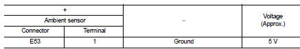
Is the inspection result normal? YES >> GO TO 2.
NO >> GO TO 4.
2.CHECK AMBIENT SENSOR GROUND CIRCUIT FOR OPEN
1. Turn ignition switch OFF.
2. Disconnect PTC heater control unit connector.
3. Check continuity between ambient sensor harness connector and A/C auto amp harness connector.
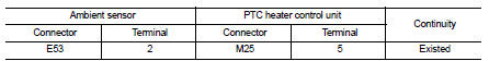
Is the inspection result normal?
YES >> GO TO 3.
NO >> Repair harness or connector.
3.CHECK AMBIENT SENSOR
Check ambient sensor. Refer to HAC-278, "Component Inspection".
Is the inspection result normal? YES >> Replace PTC heater control unit.
NO >> Replace ambient sensor.
4.CHECK AMBIENT SENSOR POWER SUPPLY CIRCUIT FOR OPEN
1. Turn ignition switch OFF.
2. Disconnect PTC heater control unit connector.
3. Check continuity between ambient sensor harness connector and PTC heater control unit harness connector.
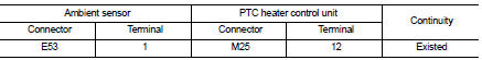
Is the inspection result normal? YES >> GO TO 5.
NO >> Repair harness or connector.
5.CHECK AMBIENT SENSOR POWER SUPPLY CIRCUIT FOR SHORT
Check continuity between ambient sensor harness connector and ground.
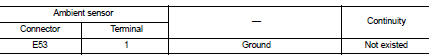
Is the inspection result normal? YES >> Replace PTC heater control unit.
NO >> Repair harness or connector.
Component Inspection
1.CHECK AMBIENT SENSOR
1. Remove ambient sensor.
2. Check resistance between ambient sensor terminals. Refer to applicable table for the normal value.
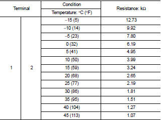
Is the inspection result normal? YES >> INSPECTION END
NO >> Replace ambient sensor.
 U1010 control unit (can)
Description
Initial diagnosis of A/C auto amp.
DTC Logic
DTC DETECTION LOGIC
DTC CONFIRMATION PROCEDURE
1.PERFORM SELF-DIAGNOSIS
With CONSULT-III
1. Turn ignition switch ON.
2. Select “Sel ...
 Power supply and ground circuit
PTC HEATER CONTROL UNIT : Diagnosis Procedure
1.CHECK FUSE
1. Turn ignition switch OFF.
2. Check 10A fuses (No. 3 and 7).
NOTE:
Refer to PG-23, "Fuse and Fusible Link Arrangement".
...
Other materials:
AEB with Pedestrian Detection system operation
Vehicle ahead detection indicator
AEB with Pedestrian Detection emergency warning indicator
AEB with Pedestrian Detection system warning light
The Automatic Emergency Braking (AEB) with Pedestrian Detection system in your Nissan Leaf is en ...
P1831 VDC operation signal
DTC Logic
DTC DETECTION LOGIC
DTC CONFIRMATION PROCEDURE
1.DTC REPRODUCTION PROCEDURE
With CONSULT-III
1. Start the engine and drive at 30 km/h (19 MPH) or more.
2. Perform self-diagnosis for “ALL MODE AWD/4WD”.
Is DTC “P1831” detected?
YES >> Proceed to diagnosis procedure ...
Three-point type seat belt
WARNING
• Every person who drives or rides in this vehicle should use a seat belt
at all times.
• Do not ride in a moving vehicle when the seatback is reclined. This can be dangerous.
The shoulder belt will not be against your body. In an accident, you could be thrown
into it and receive ...
