Nissan Juke Service and Repair Manual : P0078 EVT control solenoid valve
DTC Logic
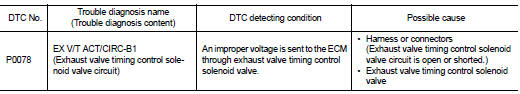
DTC DETECTION LOGIC
DTC CONFIRMATION PROCEDURE
1.PRECONDITIONING
If DTC Confirmation Procedure has been previously conducted, always perform the following procedure before conducting the next test.
1. Turn ignition switch OFF and wait at least 10 seconds.
2. Turn ignition switch ON.
3. Turn ignition switch OFF and wait at least 10 seconds.
>> GO TO2.
2.PERFORM DTC CONFIRMATION PROCEDURE
1. Start engine and let it idle for 5 seconds.
2. Check 1st trip DTC.
Is 1st trip DTC detected? YES >> Proceed to EC-585, "Diagnosis Procedure".
NO >> INSPECTION END
Diagnosis Procedure
1.CHECK EXHAUST VALVE TIMING CONTROL SOLENOID VALVE POWER SUPPLY
1. Turn ignition switch OFF.
2. Disconnect exhaust valve timing (EVT) control solenoid valve harness connector.
3. Turn ignition switch ON.
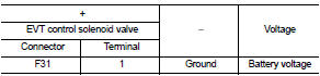
4. Check the voltage between exhaust valve timing control solenoid valve harness connector and ground.
Is the inspection result normal? YES >> GO TO 3.
NO >> GO TO 2.
2.CHECK EXHAUST VALVE TIMING CONTROL SOLENOID VALVE POWER SUPPLY CIRCUIT
1. Turn ignition switch OFF.
2. Disconnect IPDM E/R harness connector.
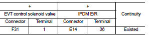
3. Check the continuity between EVT control solenoid valve harness connector and IPDM E/R harness connector.
4. Also check harness for short to ground.
Is the inspection result normal? YES >> Perform the trouble diagnosis for power supply circuit.
NO >> Repair or replace error-detected parts.
3.CHECK EXHAUST VALVE TIMING CONTROL SOLENOID VALVE GROUND CIRCUIT
1. Turn ignition switch OFF.
2. Disconnect ECM harness connector.
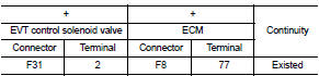
3. Check the continuity between EVT control solenoid valve harness connector and ECM harness connector.
4. Also check harness for short to ground and to power.
Is the inspection result normal? YES >> GO TO 4.
NO >> Repair or replace error-detected parts.
4.CHECK EXHAUST VALVE TIMING CONTROL SOLENOID VALVE
Check the exhaust valve timing control solenoid valve. Refer to EC-586, "Component Inspection".
Is the inspection result normal? YES >> Check intermittent incident. Refer to GI-42, "Intermittent Incident".
NO >> Replace exhaust valve timing control solenoid valve.
Component Inspection
1.CHECK EXHAUST VALVE TIMING CONTROL SOLENOID VALVE-I
1. Turn ignition switch OFF.
2. Disconnect exhaust valve timing control solenoid valve harness connector.
3. Check resistance between exhaust valve timing control solenoid valve terminals as per the following.
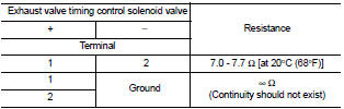
Is the inspection result normal? YES >> GO TO 2.
NO >> Replace exhaust valve timing control solenoid valve. Refer to EM-67, "Exploded View".
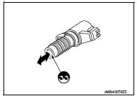
2.CHECK EXHAUST VALVE TIMING CONTROL SOLENOID VALVE-II
1. Remove exhaust valve timing control solenoid valve.
2. Provide 12 V DC between exhaust valve timing control solenoid valve terminals 1 and 2, and then interrupt it. Check that the plunger moves as shown in the figure.
CAUTION:
Do not apply 12 V DC continuously for 5 seconds or more.
Doing so may result in damage to the coil in exhaust valve timing control solenoid valve.
NOTE
:
Always replace O-ring when exhaust valve timing control
solenoid valve is removed.
Is the inspection result normal? YES >> INSPECTION END
NO >> Replace exhaust valve timing control solenoid valve. Refer to EM-67, "Exploded View".
 P0075 IVT control solenoid valve
DTC Logic
DTC DETECTION LOGIC
DTC CONFIRMATION PROCEDURE
1.PRECONDITIONING
If DTC Confirmation Procedure has been previously conducted, always turn
ignition switch OFF and wait at
least 10 se ...
 P0102, P0103 MAF SENSOR
DTC Logic
DTC DETECTION LOGIC
DTC CONFIRMATION PROCEDURE
1.PRECONDITIONING
If DTC Confirmation Procedure has been previously conducted, always turn
ignition switch OFF and wait at
least 10 se ...
Other materials:
Steering switch signal A circuit
Description
Transmits the steering switch signal to NAVI control unit.
Diagnosis Procedure
1.CHECK STEERING SWITCH SIGNAL A CIRCUIT
1. Disconnect NAVI control unit connector and spiral cable connector.
2. Check continuity between NAVI control unit harness connector and spiral cable
harness co ...
Precaution Necessary for Steering Wheel Rotation after Battery Disconnect
NOTE:
• Before removing and installing any control units, first turn the ignition
switch to the LOCK position, then disconnect
both battery cables.
• After finishing work, confirm that all control unit connectors are connected
properly, then re-connect both
battery cables.
• Always us ...
F.M.V.S.S./C.M.V.S.S. certification label
The Federal/Canadian Motor Vehicle Safety Standards (F.M.V.S.S./C.M.V.S.S.) certification
label is affixed as shown. This label contains valuable vehicle information, such
as: Gross Vehicle Weight Ratings (GVWR), Gross Axle Weight Rating (GAWR), month
and year of manufacture, Vehicle Identif ...
