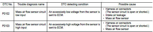
Nissan Juke Service and Repair Manual : P0102, P0103 MAF SENSOR
DTC Logic
DTC DETECTION LOGIC
DTC CONFIRMATION PROCEDURE
1.PRECONDITIONING
If DTC Confirmation Procedure has been previously conducted, always turn ignition switch OFF and wait at least 10 seconds before conducting the next test.
Which DTC is detected? P0102 >> GO TO 2.
P0103 >> GO TO 3.
2.PERFORM DTC CONFIRMATION PROCEDURE FOR DTC P0102
1. Start engine and wait at least 5 seconds.
2. Check DTC.
Is DTC detected? YES >> Go to EC-588, "Diagnosis Procedure".
NO >> INSPECTION END 3.PERFORM DTC CONFIRMATION PROCEDURE FOR DTC P0103-I
1. Turn ignition switch ON and wait at least 5 seconds.
2. Check DTC.
Is DTC detected? YES >> Go to EC-588, "Diagnosis Procedure".
NO >> GO TO 4.
4.PERFORM DTC CONFIRMATION PROCEDURE FOR DTC P0103-II
1. Start engine and wait at least 5 seconds.
2. Check DTC.
Is DTC detected? YES >> Go to EC-588, "Diagnosis Procedure".
NO >> INSPECTION END
Diagnosis Procedure
1.INSPECTION START
Confirm the detected DTC.
Which DTC is detected? P0102 >> GO TO 2.
P0103 >> GO TO 3.
2.CHECK INTAKE SYSTEM
Check the following for connection.
ŌĆó Air duct
ŌĆó Vacuum hoses
ŌĆó Intake air passage between air duct to intake manifold
Is the inspection result normal? YES >> GO TO 3.
NO >> Reconnect the parts.
3.CHECK GROUND CONNECTION
1. Turn ignition switch OFF.
2. Check ground connection E21 and E38. Refer to Ground Inspection in GI-44, "Circuit Inspection".
Is the inspection result normal? YES >> GO TO 4.
NO >> Repair or replace ground connection.
4.CHECK MAF SENSOR POWER SUPPLY CIRCUIT
1. Disconnect mass air flow (MAF) sensor harness connector.
2. Turn ignition switch ON.
3. Check the voltage between MAF sensor harness connector and ground.
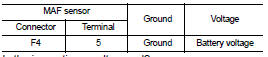
Is the inspection result normal? YES >> GO TO 5.
NO >> Repair open circuit or short to ground or short to power in harness or connectors.
5.CHECK MAF SENSOR GROUND CIRCUIT FOR OPEN AND SHORT
1. Turn ignition switch OFF.
2. Disconnect ECM harness connector.
3. Check the continuity between MAF sensor harness connector and ECM harness connector.
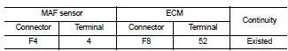
4. Also check harness for short to ground and short to power.
Is the inspection result normal? YES >> GO TO 6.
NO >> Repair open circuit or short to ground or short to power in harness or connectors.
6.CHECK MAF SENSOR INPUT SIGNAL CIRCUIT FOR OPEN AND SHORT
1. Check the continuity between MAF sensor harness connector and ECM harness connector.
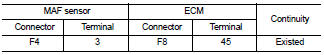
2. Also check harness for short to ground and short to power.
Is the inspection result normal? YES >> GO TO 7.
NO >> Repair open circuit or short to ground or short to power in harness or connectors.
7.CHECK MASS AIR FLOW SENSOR
Refer to EC-590, "Component Inspection".
Is the inspection result normal? YES >> GO TO 8.
NO >> Replace mass air flow sensor.
8.CHECK INTERMITTENT INCIDENT
Refer to GI-42, "Intermittent Incident".
>> INSPECTION END
Component Inspection
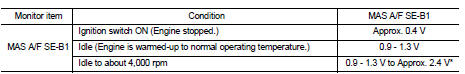
1.CHECK MASS AIR FLOW SENSOR-I
W ith CONSULT-III
1. Turn ignition switch OFF.
2. Reconnect all harness connectors disconnected.
3. Start engine and warm it up to normal operating temperature.
4. Connect CONSULT-III and select ŌĆ£DATA MONITORŌĆØ mode.
5. Select ŌĆ£MAS A/F SE-B1ŌĆØ and check indication.
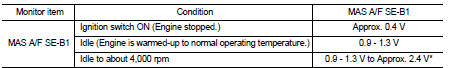
*: Check for linear voltage rise in response to engine being increased to about 4,000 rpm.
 Without CONSULT-III
1. Turn ignition switch OFF.
2. Reconnect all harness connectors disconnected.
3. Start engine and warm it up to normal operating temperature.
4. Check the voltage between ECM harness connector and ground.
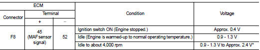
*: Check for linear voltage rise in response to engine being increased to about 4,000 rpm.
Is the inspection result normal? YES >> INSPECTION END
NO >> GO TO 2.
2.CHECK FOR THE CAUSE OF UNEVEN AIR FLOW THROUGH MASS AIR FLOW SENSOR
1. Turn ignition switch OFF.
2. Check for the cause of uneven air flow through mass air flow sensor. Refer to the following.
- Crushed air ducts
- Malfunctioning seal of air cleaner element
- Uneven dirt of air cleaner element
- Improper specification of intake air system parts
Is the inspection result normal? YES >> GO TO 4.
NO >> GO TO 3.
3.CHECK MASS AIR FLOW SENSOR-II
 With CONSULT-III
1. Repair or replace malfunctioning part.
2. Start engine and warm it up to normal operating temperature.
3. Connect CONSULT-III and select ŌĆ£DATA MONITORŌĆØ mode.
4. Select ŌĆ£MAS A/F SE-B1ŌĆØ and check indication.
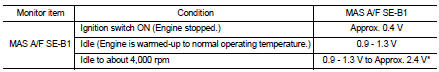
*: Check for linear voltage rise in response to engine being increased to about 4,000 rpm.
 Without CONSULT-III
1. Repair or replace malfunctioning part.
2. Start engine and warm it up to normal operating temperature.
3. Check the voltage between ECM harness connector and ground.
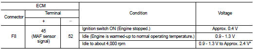
*: Check for linear voltage rise in response to engine being increased to about 4,000 rpm.
Is the inspection result normal? YES >> INSPECTION END
NO >> GO TO 4.
4.CHECK MASS AIR FLOW SENSOR-III
 With CONSULT-III
1. Turn ignition switch OFF.
2. Disconnect mass air flow sensor harness connector and reconnect it again.
3. Start engine and warm it up to normal operating temperature.
4. Connect CONSULT-III and select ŌĆ£DATA MONITORŌĆØ mode.
5. Select ŌĆ£MAS A/F SE-B1ŌĆØ and check indication.
*: Check for linear voltage rise in response to engine being increased to about 4,000 rpm.
 Without CONSULT-III
1. Turn ignition switch OFF.
2. Disconnect mass air flow sensor harness connector and reconnect it again.
3. Start engine and warm it up to normal operating temperature.
4. Check the voltage between ECM harness connector and ground.
*: Check for linear voltage rise in response to engine being increased to about 4,000 rpm.
Is the inspection result normal? YES >> INSPECTION END
NO >> Clean or replace mass air flow sensor.
 P0078 EVT control solenoid valve
DTC Logic
DTC DETECTION LOGIC
DTC CONFIRMATION PROCEDURE
1.PRECONDITIONING
If DTC Confirmation Procedure has been previously conducted, always perform
the following procedure
before conductin ...
 P0112, P0113 IAT SENSOR
DTC Logic
DTC DETECTION LOGIC
DTC CONFIRMATION PROCEDURE
1.PRECONDITIONING
If DTC Confirmation Procedure has been previously conducted, always turn
ignition switch OFF and wait at
least 10 se ...
Other materials:
Starting difficult with cold engine
Description
CHART 3: STARTING DIFFICULT WITH COLD ENGINE
Diagnosis Procedure
1.CHECK ENGINE OIL LEVEL
Is the engine oil level correct?
Yes or No
Yes >> GO TO 2.
No >> Top up the oil.
2.CHECK ENGINE OIL
Check the grade of engine oil. Refer to LU-33, "Inspection".
...
P0715 input speed sensor A
DTC Logic
DTC DETECTION LOGIC
DTC CONFIRMATION PROCEDURE
CAUTION:
Always drive vehicle at a safe speed.
NOTE:
If ŌĆ£DTC CONFIRMATION PROCEDUREŌĆØ has been previously performed, always turn
ignition switch
OFF and wait at least 10 seconds before performing the next test.
After the repai ...
Diagnosis system (BCM) (without intelligent key system)
Common item
COMMON ITEM : CONSULT-III Function (BCM - COMMON ITEM)
APPLICATION ITEM
CONSULT-III performs the following functions via CAN communication with BCM.
SYSTEM APPLICATION
BCM can perform the following functions for each system.
NOTE:
It can perform the diagnosis modes except the ...
