Nissan Juke Service and Repair Manual : Power supply and ground circuit
PTC HEATER CONTROL UNIT : Diagnosis Procedure
1.CHECK FUSE
1. Turn ignition switch OFF.
2. Check 10A fuses (No. 3 and 7).
NOTE
:
Refer to PG-23, "Fuse and Fusible Link Arrangement".
Is the inspection result normal? YES >> GO TO 2.
NO >> Replace the blown fuse after repairing the affected circuit if a fuse is blown.
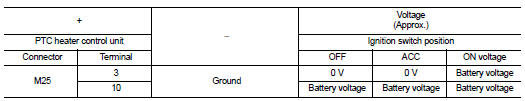
2.CHECK PTC HEATER CONTROL UNIT POWER SUPPLY
1. Disconnect PTC heater control unit connector.
2. Check voltage between PTC heater control unit harness connector and ground.
Is the inspection result normal? YES >> GO TO 3.
NO >> Repair harness or connector between PTC heater control unit and fuse.
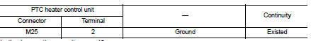
3.CHECK PTC HEATER CONTROL UNIT GROUND CIRCUIT FOR OPEN
1. Turn ignition switch OFF.
2. Check continuity between PTC heater control unit harness connector and ground.
Is the inspection result normal? YES >> Replace PTC heater control unit.
NO >> Repair harness or connector.
 B257B, B257C ambient sensor
DTC Logic
DTC DETECTION LOGIC
NOTE:
ÔÇó If DTC is displayed along with DTC U1000, first perform the trouble diagnosis
for DTC U1000. Refer to HAC-
275, "DTC Logic".
ÔÇó If DTC is disp ...
 A/C switch
Component Function Check
1.CHECK A/C ON SIGNAL
With CONSULT-III
1. Turn ignition switch ON.
2. Select ÔÇťAIR CONDITIONERÔÇŁ of ÔÇťBCMÔÇŁ using CONSULT-III.
3. Select ÔÇťAIR COND SWÔÇŁ in ÔÇťDATA ...
Other materials:
Information display (speed limiter))
Component Function Check
1.CHECK INFORMATION DISPLAY (SPEED LIMITER) FUNCTION
1. Start engine.
2. Press speed limiter MAIN switch.
3. Drive the vehicle at more than 30 km/h (20 MPH).
CAUTION:
Always drive vehicle at a safe speed.
4. Press SET/ACCELERATE or SET/COAST switch.
5. Perform a te ...
Can communication
CAN COMMUNICATION : System Description
CAN (Controller Area Network) is a serial communication line for real time
application. It is an on-vehicle multiplex
communication line with high data communication speed and excellent error
detection ability. Many electronic
control units are equipped ...
Component parts
Manual air conditioning system : Component Part Location
1. BCM
ÔÇó With Intelligent Key: Refer to BCS-
6, "BODY CONTROL SYSTEM :
Component Parts Location".
ÔÇó Without Intelligent Key: Refer to
BCS-161, "Removal and Installation".
2. Magnet clutch
3. Refrigerant press ...
