Nissan Juke Service and Repair Manual : A/C switch
Component Function Check
1.CHECK A/C ON SIGNAL
 With CONSULT-III
1. Turn ignition switch ON.
2. Select “AIR CONDITIONER” of “BCM” using CONSULT-III.
3. Select “AIR COND SW” in “DATA MONITOR” mode, and check status under the following condition.
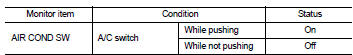
Is the inspection result normal? YES >> INSPECTION END
NO >> Refer to HAC-281, "Diagnosis Procedure".
Diagnosis Procedure
1.CHECK A/C SWITCH POWER SUPPLY
1. Turn ignition switch OFF.
2. Disconnect A/C control connector.
3. Turn ignition switch ON.
4. Check output waveform between A/C control harness connector and ground with using oscilloscope.
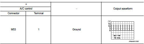
Is the inspection result normal? YES >> GO TO 2.
NO >> GO TO 3.
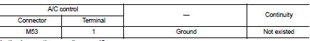
2.CHECK A/C SWITCH GROUND CIRCUIT FOR OPEN
1. Turn ignition switch OFF.
2. Disconnect BCM connector.
3. Check continuity between A/C control harness connector and ground.
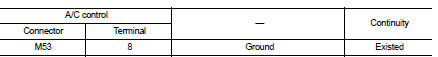
Is the inspection result normal? YES >> Replace A/C control. Refer to HAC-239, "Removal and Installation".
NO >> Repair harness or connector.
3.CHECK A/C SWITCH POWER SUPPLY CIRCUIT FOR OPEN
1. Turn ignition switch OFF.
2. Disconnect BCM connector.
3. Check continuity between A/C control harness connector and BCM harness connector.
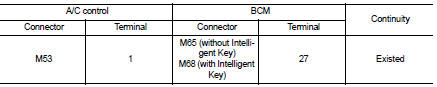
Is the inspection result normal? YES >> GO TO 4.
NO >> Repair harness or connector.
4.CHECK A/C SWITCH POWER SUPPLY CIRCUIT FOR SHORT
Check continuity between A/C control harness connector and ground.
Is the inspection result normal? YES >> Replace BCM. Refer to BCS-93, "Removal and Installation" (with Intelligent Key) or BCS-161, "Removal and Installation" (without Intelligent Key).
NO >> Repair harness or connector.
 Power supply and ground circuit
PTC HEATER CONTROL UNIT : Diagnosis Procedure
1.CHECK FUSE
1. Turn ignition switch OFF.
2. Check 10A fuses (No. 3 and 7).
NOTE:
Refer to PG-23, "Fuse and Fusible Link Arrangement".
...
 Blower fan on signal
Component Function Check
1.CHECK BLOWER FAN ON SIGNAL
With CONSULT-III
1. Turn ignition switch ON.
2. Select “AIR CONDITIONER” of “BCM” using CONSULT-III.
3. Select “FAN ON SIG” in †...
Other materials:
Power supply and ground circuit
Diagnosis Procedure
1.CHECK 4WD CONTROL MODULE POWER SUPPLY (1)
1. Turn the ignition switch OFF.
2. Disconnect 4WD control module harness connector.
3. Check the voltage between 4WD control module harness connector and ground.
4. Turn the ignition switch ON.
CAUTION:
Never start the engin ...
Seatback Pocket
The convenient seatback pockets may be located on the rear of the driver's and/or front passenger's seat. These fabric pockets can be used to store maps, magazines, lightweight travel documents, or small electronics safely within reach of rear-seat occupants.
WARNING
...
Normal operating condition
Description
RELATED TO AUDIO
• The majority of the audio malfunctions are the result of outside causes
(bad CD, electromagnetic interference,
etc.). Check the symptoms below to diagnose the malfunction.
• The vehicle itself can be a source of noise if noise prevention parts or
electrical ...
