Nissan Juke Service and Repair Manual : Blower fan on signal
Component Function Check
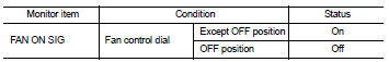
1.CHECK BLOWER FAN ON SIGNAL
 With CONSULT-III
1. Turn ignition switch ON.
2. Select ÔÇťAIR CONDITIONERÔÇŁ of ÔÇťBCMÔÇŁ using CONSULT-III.
3. Select ÔÇťFAN ON SIGÔÇŁ in ÔÇťDATA MONITORÔÇŁ mode, and check status under the following condition.
Is the inspection result normal? YES >> INSPECTION END
NO >> Refer to HAC-283, "Diagnosis Procedure".
Diagnosis Procedure
1.CHECK FAN SWITCH POWER SUPPLY SIGNAL
1. Turn ignition switch OFF.
2. Disconnect A/C control harness connector.
3. Turn ignition switch ON.
4. Check output waveform between A/C control and ground with using oscilloscope.
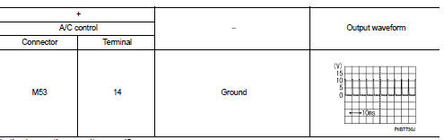
Is the inspection result normal? YES >> Replace A/C control. Refer to HAC-304, "Removal and Installation".
NO >> GO TO 2.
2.CHECK BLOWER FAN ON SIGNAL CIRCUIT FOR OPEN
1. Turn ignition switch OFF.
2. Disconnect BCM connector.
3. Check continuity A/C control harness connector and BCM harness connector.
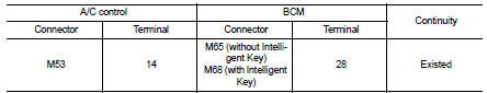
Is the inspection result normal? YES >> GO TO 3.
NO >> Repair harness or connector.
3.CHECK BLOWER FAN ON SIGNAL CIRCUIT FOR SHORT
Check continuity between A/C control harness connector and ground.
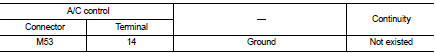
Is the inspection result normal? YES >> Replace BCM. Refer to BCS-93, "Removal and Installation" (with Intelligent Key) or BCS-161, "Removal and Installation" (without Intelligent Key).
NO >> Repair harness or connector.
 A/C switch
Component Function Check
1.CHECK A/C ON SIGNAL
With CONSULT-III
1. Turn ignition switch ON.
2. Select ÔÇťAIR CONDITIONERÔÇŁ of ÔÇťBCMÔÇŁ using CONSULT-III.
3. Select ÔÇťAIR COND SWÔÇŁ in ÔÇťDATA ...
 Thermo control amplifier
Component Function Check
1.CHECK A/C ON SIGNAL
With CONSULT-III
1. Turn ignition switch ON.
2. Select ÔÇťAIR CONDITIONERÔÇŁ of ÔÇťBCMÔÇŁ using CONSULT-III.
3. Select ÔÇťTHERMO AMPÔÇŁ in ÔÇťDATA M ...
Other materials:
Battery
Exploded View
1 : Battery fix frame
:N┬Ěm (kg-m, in-lb)
Removal and Installation
REMOVAL
1. Disconnect the battery cable from the negative terminal.
CAUTION:
When disconnecting, disconnect the battery cable from the negative terminal
first.
2. Remove cover of battery positive termi ...
P1611 ID discord, IMMU-ECM
DTC Logic
DTC DETECTION LOGIC
DTC CONFIRMATION PROCEDURE
1.PERFORM DTC CONFIRMATION PROCEDURE
1. Turn ignition switch ON.
2. Check DTC in ÔÇťSelf Diagnostic ResultÔÇŁ mode of ÔÇťENGINEÔÇŁ using CONSULT-III.
Is DTC detected?
YES >> Go to SEC-53, "Diagnosis Procedure".
NO ...
Door cable
Exploded View
LEFT SIDE
1. A/C unit assembly
2. Intake door lever
3. Intake door link
4. Intake door cable
5. Air mix door cable
6. Air mix door link
7. Air mix door rod
8. Lower air mix door lever
9. Upper air mix door lever
10. Max. cool door
A. To A/C control
RIGHT SIDE
...
