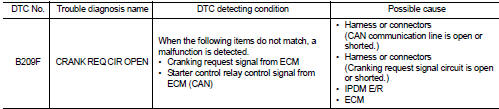
Nissan Juke Service and Repair Manual : B209F cranking request circuit
DTC Logic
DTC DETECTION LOGIC
NOTE
:
If DTC B209F is displayed with DTC U1000, first perform the trouble diagnosis
for DTC U1000. Refer to PCS-
30, "DTC Logic".
DTC CONFIRMATION PROCEDURE
1.PERFORM DTC CONFIRMATION PROCEDURE
1. Perform DTC CONFIRMATION PROCEDURE for DTC P1650. Refer to EC-366, "DTC Logic" (MR16DDT) or EC-725, "DTC Logic" (HR16DE).
2. Turn ignition switch ON.
3. Check DTC in “Self Diagnostic Result” mode of “IPDM E/R” using CONSULT-III.
Is DTC detected? YES >> Refer to SEC-134, "Diagnosis Procedure".
NO >> INSPECTION END
Diagnosis Procedure
1.CHECK CRANKING REQUEST SIGNAL
1. Turn ignition switch ON.
2. Check voltage between IPDM E/R harness connector and ground under the following conditions.
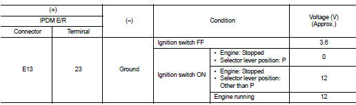
Is the inspection result normal? YES >> GO TO 3.
NO >> GO TO 2.
2.CHECK CRANKING REQUEST SIGNAL CIRCUIT
1. Turn ignition switch OFF.
2. Disconnect IPDM E/R connector.
3. Disconnect ECM connector.
4. Check continuity between IPDM E/R harness connector and ECM harness connector.
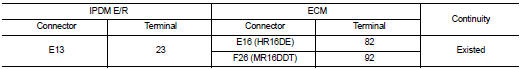
5. Check continuity between BCM harness connector and ground.
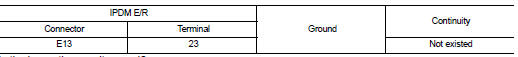
Is the inspection result normal? YES >> GO TO 3.
NO >> Repair or replace harness.
3.REPLACE IPDM E/R
1. Replace IPDM E/R. Refer to PCS-34, "Removal and Installation".
2. Perform DTC CONFIRMATION PROCEDURE for DTC B209F. Refer to SEC-134, "DTC Logic".
Is DTC detected? YES >> GO TO 4.
NO >> INSPECTION END
4.REPLACE ECM
Replace ECM.
Refer to EC-447, "Removal and Installation" (MR16DDT) or EC-805, "Removal and Installation" (HR16DE).
>> INSPECTION END
 B26FC key registration
DTC Logic
DTC DETECTION LOGIC
DTC CONFIRMATION PROCEDURE
1.PERFORM DTC CONFIRMATION PROCEDURE
1. Perform initialization of BCM and reregistration of all Intelligent Keys
using CONSULT-III.
...
 B20A0 cranking request circuit
DTC Logic
DTC DETECTION LOGIC
NOTE:
If DTC B20A0 is displayed with DTC U1000, first perform the trouble diagnosis
for DTC U1000. Refer to PCS-
30, "DTC Logic".
DTC CONFIRMATION PROC ...
Other materials:
Service regeneration
Description
Service Regeneration is performed with CONSULT-III to reduce particulate
matter in diesel particulate filter.
Service Regeneration should be performed in the following cases.
• ECM enters fail-safe mode because the amount of particulate matter in diesel
particulate filter reac ...
Component parts
CVT control system : Component Parts Location
1. Multi display unit (MDU)*
Refer to DMS-3, "Component Parts
Location".
2. Combination meter 3. Manual mode indicator
(On the combination meter)
4. Shift position indicator
(On the combination meter)
5. Malfunction indicator lamp (MI ...
Test Value and Test Limit
The following is the information specified in Service $06 of ISO 15031-5.
The test value is a parameter used to determine whether a system/circuit
diagnostic test is OK or NG while
being monitored by the ECM during self-diagnosis. The test limit is a reference
value which is specified as the ...
