Nissan Juke Service and Repair Manual : B20A0 cranking request circuit
DTC Logic
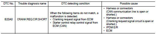
DTC DETECTION LOGIC
NOTE
:
If DTC B20A0 is displayed with DTC U1000, first perform the trouble diagnosis
for DTC U1000. Refer to PCS-
30, "DTC Logic".
DTC CONFIRMATION PROCEDURE
1.PERFORM DTC CONFIRMATION PROCEDURE
1. Perform DTC CONFIRMATION PROCEDURE for DTC P1650. Refer to EC-366, "DTC Logic" (MR16DDT) or EC-725, "DTC Logic" (HR16DE).
2. Turn ignition switch ON.
3. Check DTC in ÔÇťSelf Diagnostic ResultÔÇŁ mode of ÔÇťIPDM E/RÔÇŁ using CONSULT-III.
Is DTC detected? YES >> Refer to SEC-136, "Diagnosis Procedure".
NO >> INSPECTION END
Diagnosis Procedure
1.CHECK CRANKING REQUEST SIGNAL
1. Turn ignition switch ON.
2. Check voltage between IPDM E/R harness connector and ground under the following conditions.
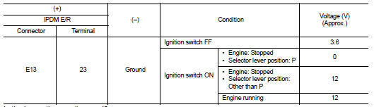
Is the inspection result normal? YES >> GO TO 3.
NO >> GO TO 2.
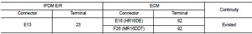
2.CHECK CRANKING REQUEST SIGNAL CIRCUIT
1. Turn ignition switch OFF.
2. Disconnect IPDM E/R connector.
3. Disconnect ECM connector.
4. Check continuity between IPDM E/R harness connector and ECM harness connector.
5. Check continuity between BCM harness connector and ground.
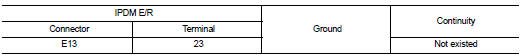
Is the inspection result normal? YES >> GO TO 3.
NO >> Repair or replace harness.
3.REPLACE IPDM E/R
1. Replace IPDM E/R. Refer to PCS-34, "Removal and Installation".
2. Perform DTC CONFIRMATION PROCEDURE for DTC B20A0. Refer to SEC-136, "DTC Logic".
Is DTC detected? YES >> GO TO 4.
NO >> INSPECTION END
4.REPLACE ECM
Replace ECM.
Refer to EC-447, "Removal and Installation" (MR16DDT) or EC-805, "Removal and Installation" (HR16DE).
>> INSPECTION END
 B209F cranking request circuit
DTC Logic
DTC DETECTION LOGIC
NOTE:
If DTC B209F is displayed with DTC U1000, first perform the trouble diagnosis
for DTC U1000. Refer to PCS-
30, "DTC Logic".
DTC CONFIRMATION PROC ...
 B2108 steering lock relay
DTC Logic
DTC DETECTION LOGIC
NOTE:
If DTC B2108 is displayed with DTC U1000, first perform the trouble diagnosis
for DTC U1000. Refer to PCS-
30, "DTC Logic".
DTC CONFIRMATION PROC ...
Other materials:
Camshaft
*: Total indicator reading
Valve Lifter
Valve Clearance
*:Approximately 80┬░C (176┬░F)
Available Valve Lifter
...
Security indicator lamp
Component Function Check
1.CHECK FUNCTION
1. Perform ÔÇťTHEFT INDÔÇŁ in the ÔÇťACTIVE TESTÔÇŁ mode of ÔÇťBCMÔÇŁ using
CONSULT-III.
2. Check security indicator lamp operation.
Is the inspection result normal?
YES >> INSPECTION END
NO >> Go to SEC-227, "Diagnosis Procedure&q ...
Sample/Wiring Diagram -Example-
Each section includes wiring diagrams.
Description
SWITCH POSITIONS
Switches are shown in wiring diagrams as if the vehicle is in the ÔÇťnormalÔÇŁ
condition.
A vehicle is in the ÔÇťnormalÔÇŁ condition when:
ÔÇó ignition switch is ÔÇťOFFÔÇŁ,
ÔÇó doors, hood and trunk lid/back door are ...
