Nissan Juke Service and Repair Manual : Injection tube and fuel injector
Exploded View
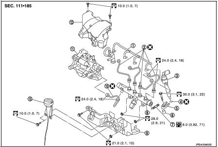
1. Spill hose
2. Injection tube
3. Fuel injector
4. Heat protection washer
5. Fuel injector bracket
6. Fuel injector bracket spacer
7. Fuel rail stud bolt
8. Fuel rail
9. High pressure protection cover (lower)
10. Injection tube
11. High pressure supply pump
12. High pressure protection cover (upper)
13. Oil level gauge guide
 : N·m (kg-m, ft-lb)
 : N·m (kg-m, in-lb)
 : Always replace after every
disassembly.
Removal and Installation
REMOVAL
CAUTION:
• Be sure to read “Precautions for Diesel Equipment”. Refer to EM-263,
"Precaution for Diesel Equipment".
• Wait until the fuel temperature drops before carrying out any work.
• Order the special high pressure injection circuit plug kit.
• It is forbidden to open an injector. If you open an injector by mistake, you will have to change it. This is because of the manufacturing and installation tolerances and because there is a risk of contaminating the inside of the injector.
• The rod filter of the injector must not be removed.
NOTE:
It is possible to replace a single injection tube.
1. Disconnect the battery cable from negative terminal.
2. Remove air inlet tube assembly and air inlet tube. Refer to EM-281, "Exploded View".
3. Remove oil level gauge guide and plug the hole.
4. Remove injection tube protection cover.
5. Remove the neck located on the fuel rail, NOTE
:
Undo the nut on the pump side or the injector side, then the nut located on the
rail side. Undo the
nuts for each pipe in turn. Move the nut along the pipe keeping the olive in
contact with the taper.
6. Remove all the injection tubes.
7. Plug all the holes in the injection circuit.
8. Remove fuel rail.
9. Disconnect fuel return pipe.
10. Manually remove the injector diesel return hose.
CAUTION:
Do not force on the diesel injector return hose
11. Plug all the holes of the injection circuit.
12. Disconnect the injector harness connector.
13. Unscrew the injector bracket.
14. Remove the injector.
15. Pull off the flame shield washer.
INSTALLATION
CAUTION:
All the injection tubes removed must be systematically replaced.
1. Clean the injector sockets and the injector bodies, as well as their brackets using a lint-free cloth (use the wipes recommended for this purpose, dipped in clean solvent.
2. Dry off using a different new wipe.
3. Replace the flame shield washer with a new one.
4. Position the injector.
5. Tighten its mounting bracket.
 : 30.0 N·m (3.1 kg-m, 22 ft-lb)
6. Install injection tubes with new one.
7. Finger tightens the nuts.
8. Before fitting the new injection tubes, lightly lubricate the nut threads with the oil from the sachet provided in the new parts kit.
NOTE
:
Fit the pump/rail pipe before the rail/injector tubes.
9. Fit the pump-rail injection tube as follow: • Remove the protective plugs from the high pressure pump outlet, the high pressure rail inlet and the pipe.
• Insert the injection tube olive into the taper of the high pressure pump
outlet,
• Insert the injection tube olive into the taper of the high pressure rail
inlet.
• Finger tighten the nuts of the injection tube starting with the one located on the rail side.
10. Install the rail-injector injection tube.
11. Tighten the injection tube nut.
 : 24.0 N·m (2.4 kg-m, 18 ft-lb)
12. Connect fuel return pipe.
13. Install in the reverse order to removal for the other refitting operations.
 Vacuum pump
Exploded View
1. Vacuum pump
2. Gasket
3. Damper valve bracket
4. Vacuum hose
A. To electric throttle control actuator
Engine front
: N·m (kg-m, ft-lb)
: Always replace after every
dis ...
 5TH injector
Exploded View
1. 5th injector retaining bracket
2. 5th injector bolt
3. 5th injector
4. Injector seal
5. Diesel injector cooler
6. Gasket
7. Turbocharger outlet duct
: N·m (kg-m, ft-lb) ...
Other materials:
Does not operate
Description
ESP function, TCS function, ABS function, EBD function and brake limited slip
differential (BLSD) function
does not operate.
Diagnosis Procedure
CAUTION:
• ESP function, TCS function, ABS function, EBD function and brake limited slip
differential (BLSD)
function never operate ...
U1000, U1001 CAN COMM CIRCUIT
Description
CAN (Controller Area Network) is a serial communication line for real time
application. It is an on-vehicle multiplex
communication line with high data communication speed and excellent error
detection ability. Many electronic
control units are equipped onto a vehicle, and each co ...
System
Headlamp system
HEADLAMP SYSTEM : System Diagram
HEADLAMP SYSTEM : System Description
OUTLINE
Headlamp is controlled by combination switch reading function and headlamp
control function of BCM, and
relay control function of IPDM E/R.
HEADLAMP (LO) OPERATION
• BCM detects the combinati ...
