Nissan Juke Service and Repair Manual : Vacuum pump
Exploded View
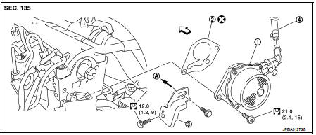
1. Vacuum pump
2. Gasket
3. Damper valve bracket
4. Vacuum hose
A. To electric throttle control actuator
 Engine front
 : N·m (kg-m, ft-lb)
 : Always replace after every
disassembly.
Removal and Installation
REMOVAL
1. Remove air cleaner case. Refer to EM-280, "Exploded View".
2. Disconnect vacuum hose from vacuum pump side.
3. Remove damper valve bracket.
4. Remove vacuum pump.
INSTALLATION
Install in the reverse order of removal.
Inspection
INSPECTION BEFORE REMOVAL
1. Disconnect vacuum hose, and connect a vacuum gauge via 3-way connector.
• Disconnect point where vacuum from vacuum pump can be measured directly and install 3-way connector.
2. Start engine and measure generated vacuum at idle speed.
Standard : -86.6 to -101.3 kPa (-866 to -1,013 mbar, -650 to -760 mmHg, -25.59 to -29.92 inHg)
 Glow plug
Exploded View
1. Glow plug
Engine front
: N·m (kg-m, ft-lb)
Removal and Installation
REMOVAL
CAUTION:
Remove glow plug only if necessary. If carbon adheres, it may be stuck and
broken.
1 ...
 Injection tube and fuel injector
Exploded View
1. Spill hose
2. Injection tube
3. Fuel injector
4. Heat protection washer
5. Fuel injector bracket
6. Fuel injector bracket spacer
7. Fuel rail stud bolt
8. Fuel rail
9 ...
Other materials:
Removal and installation
Exhaust system
Exploded View
2WD
1. Center muffler
2. Mounting rubber
3. Spring
4. Seal bearing
5. Stud bolt
6. Three way catalyst
7. Heated oxygen sensor 2
8. Seal bearing
9. Ring gasket
10. Main muffler
A. To catalyst convertor
: N·m (kg-m, ft-lb)
: Always replace after eve ...
Key ID warning does not operate
Diagnosis Procedure
1.CHECK DTC WITH BCM AND COMBINATION METER
Check that DTC is not detected with BCM and combination meter.
Is the inspection result normal?
YES >> GO TO 2.
NO-1 >> Refer to BCS-67, "DTC Index". (BCM)
NO-2 >> Refer to MWI-36, "DTC Index&qu ...
Injection tube and fuel injector
Exploded View
1. Spill hose
2. Injection tube
3. Fuel injector
4. Heat protection washer
5. Fuel injector bracket
6. Fuel injector bracket spacer
7. Fuel rail stud bolt
8. Fuel rail
9. High pressure protection cover (lower)
10. Injection tube
11. High pressure supply pump
12. H ...
