Nissan Juke Owners Manual : Adjust
For adjustable head restraint/headrest
Adjust the head restraint/headrest so the center is level with the center of your ears. If your ear position is still higher than the recommended alignment, place the head restraint/headrest at the highest position.
For non-adjustable head restraint/headrest
Make sure the head restraint/headrest is positioned so the lock knob is engaged in the notch before riding in that designated seating position.
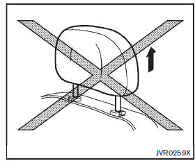
Raise
To raise the head restraint/headrest, pull it up.
Make sure the head restraint/headrest is positioned so the lock knob is engaged in the notch before riding in that designated seating position
Lower
To lower, push and hold the lock knob and push the head restraint/headrest down.
Make sure the head restraint/headrest is positioned so the lock knob is engaged in the notch before riding in that designated seating position.
 Install
1. Align the head restraint/headrest stalks with the holes in the seat. Make
sure that the head restraint/headrest is facing the correct direction. The stalk
with the adjustment notch1 must be i ...
 Front-seat Active Head Restraints
The Active Head Restraint moves forward utilizing the force that the seatback
receives from the occupant in a rear-end collision. The movement of the head restraint
helps support the occupant’ ...
Other materials:
Front door
Exploded View
1. Front door panel
2. Grommet
3. TORX bolt
4. Door striker
5. Door pad
6. Bumper rubber
7. Door check link
8. Door hinge (lower)
9. Door hinge (upper)
10. Grommet
: Do not reuse
: N·m (kg-m, in-lb)
: N·m (kg-m, ft-lb)
: Body grease
Door assembly
DOOR ASSEMBLY ...
Radiator cap : Inspection
• Check valve seat (A) of radiator cap.
B : Metal plunger
- Check that valve seat is swollen to the extent that the edge of the
plunger cannot be seen when watching it vertically from the top.
- Check that valve seat has no soil and damage.
• Pull negative-pressure valve to open it, and t ...
P1225 TP sensor
DTC Logic
DTC DETECTION LOGIC
DTC CONFIRMATION PROCEDURE
1.PRECONDITIONING
If DTC Confirmation Procedure has been previously conducted, always perform
the following procedure
before conducting the next test.
1. Turn ignition switch OFF and wait at least 10 seconds.
2. Turn ignition swit ...
