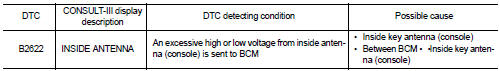
Nissan Juke Service and Repair Manual : B2622 inside antenna
DTC Logic
DTC DETECTION LOGIC
DTC CONFIRMATION PROCEDURE
1.PERFORM DTC CONFIRMATION PROCEDURE
1. Select “INTELLIGENT KEY” of “BCM” using CONSULT-III.
2. Select “INSIDE ANT DIAGNOSIS” in “WORK SUPPORT” mode.
3. Perform inside key antenna (“INSIDE ANT DIAGNOSIS”) on “WORK SUPPORT” of “INTELLIGENT KEY”.
4. Check BCM for DTC.
Is inside key antenna DTC detected? YES >> Refer to DLK-57, "Diagnosis Procedure".
NO >> Inside key antenna (console) is OK.
Diagnosis Procedure
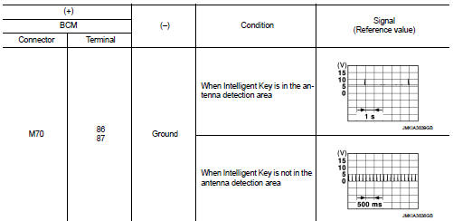
1.CHECK INSIDE KEY ANTENNA INPUT SIGNAL 1
1. Turn ignition switch ON.
2. Check signal between BCM harness connector and ground using oscilloscope.
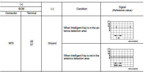
Is the inspection result normal? YES >> Replace BCM. Refer to BCS-93, "Removal and Installation".
NO >> GO TO 2.
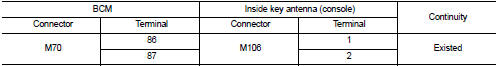
2.CHECK INSIDE KEY ANTENNA CIRCUIT
1. Turn ignition switch OFF.
2. Disconnect BCM connector and inside key antenna (console) connector.
3. Check continuity between BCM harness connector and inside key antenna (console) harness connector.
4. Check continuity between BCM harness connector and ground.
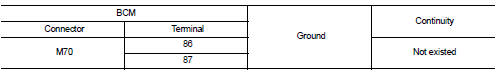
Is the inspection result normal? YES >> GO TO 3.
NO >> Repair or replace harness.
3.CHECK INSIDE KEY ANTENNA INPUT SIGNAL 2
1. Replace inside key antenna (console). (New antenna or other antenna) 2. Connect BCM connector and inside key antenna (console) connector.
3. Turn ignition switch ON.
4. Check signal between BCM harness connector and ground using oscilloscope.
Is the inspection result normal? YES >> Replace inside key antenna (console).
NO >> Replace BCM. Refer to BCS-93, "Removal and Installation".
 B2621 inside antenna
DTC Logic
DTC DETECTION LOGIC
DTC CONFIRMATION PROCEDURE
1.PERFORM DTC CONFIRMATION PROCEDURE
1. Select “INTELLIGENT KEY” of “BCM” using CONSULT-III.
2. Select “INSIDE ANT DIAGNOSIS†...
 B2623 inside antenna
DTC Logic
DTC DETECTION LOGIC
DTC CONFIRMATION PROCEDURE
1.PERFORM DTC CONFIRMATION PROCEDURE
1. Select “INTELLIGENT KEY” of “BCM” using CONSULT-III.
2. Select “INSIDE ANT DIAGNOSIS†...
Other materials:
C1110 ABS actuator and electric unit (control unit)
DTC Logic
DTC DETECTION LOGIC
DTC CONFIRMATION PROCEDURE
1.PRECONDITIONING
If “DTC CONFIRMATION PROCEDURE” has been previously conducted, always turn
ignition switch OFF and
wait at least 10 seconds before conducting the next test.
>> GO TO 2.
2.CHECK DTC DETECTION
With CON ...
Sample/Wiring Diagram -Example-
Each section includes wiring diagrams.
Description
SWITCH POSITIONS
Switches are shown in wiring diagrams as if the vehicle is in the “normal”
condition.
A vehicle is in the “normal” condition when:
• ignition switch is “OFF”,
• doors, hood and trunk lid/back door are ...
Vehicle speed sensing auto lock operation does not operate
Diagnosis Procedure
1.CHECK “AUTOMATIC LOCK/UNLOCK SELECT” SETTING IN “WORK SUPPORT”
1. Select “DOOR LOCK” of “BCM” using CONSULT-III.
2. Select “AUTOMATIC LOCK/UNLOCK SELECT” in “WORK SUPPORT” mode.
3. Check “AUTOMATIC LOCK/UNLOCK SELECT” in “WORK SUPPORT”.
Re ...
