Nissan Juke Service and Repair Manual : B2621 inside antenna
DTC Logic
DTC DETECTION LOGIC

DTC CONFIRMATION PROCEDURE
1.PERFORM DTC CONFIRMATION PROCEDURE
1. Select “INTELLIGENT KEY” of “BCM” using CONSULT-III.
2. Select “INSIDE ANT DIAGNOSIS” in “WORK SUPPORT” mode.
3. Perform inside key antenna (“INSIDE ANT DIAGNOSIS”) on “WORK SUPPORT” of “INTELLIGENT KEY”.
4. Check BCM for DTC.
Is inside key antenna DTC detected? YES >> Refer to DLK-55, "Diagnosis Procedure".
NO >> Inside key antenna (instrument center) is OK.
Diagnosis Procedure
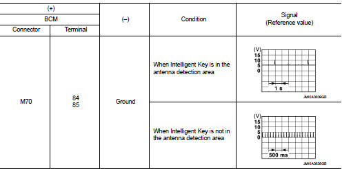
1.CHECK INSIDE KEY ANTENNA INPUT SIGNAL 1
1. Turn ignition switch ON.
2. Check signal between BCM harness connector and ground using oscilloscope.

Is the inspection result normal? YES >> Replace BCM. Refer to BCS-93, "Removal and Installation".
NO >> GO TO 2.
2.CHECK INSIDE KEY ANTENNA CIRCUIT
1. Turn ignition switch OFF.
2. Disconnect BCM connector and inside key antenna (instrument center) connector.
3. Check continuity between BCM harness connector and inside key antenna (instrument center) harness connector.

4. Check continuity between BCM harness connector and ground.

Is the inspection result normal? YES >> GO TO 3.
NO >> Repair or replace harness.
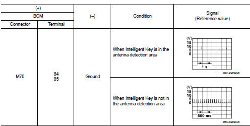
3.CHECK INSIDE KEY ANTENNA INPUT SIGNAL 2
1. Replace inside key antenna (instrument center). (New antenna or other
antenna)
2. Connect BCM connector and inside key antenna (instrument center) connector.
3. Turn ignition switch ON.
4. Check signal between BCM harness connector and ground using oscilloscope.

Is the inspection result normal? YES >> Replace inside key antenna (instrument center).
NO >> Replace BCM. Refer to BCS-93, "Removal and Installation".
 B2622 inside antenna
DTC Logic
DTC DETECTION LOGIC
DTC CONFIRMATION PROCEDURE
1.PERFORM DTC CONFIRMATION PROCEDURE
1. Select “INTELLIGENT KEY” of “BCM” using CONSULT-III.
2. Select “INSIDE ANT DIAGNOSIS” in “WORK S ...
Other materials:
Clutch master cylinder
LHD : Exploded View
1. Reservoir hose
2. Reservoir tank
3. Master cylinder
LHD : Removal and Installation
REMOVAL
CAUTION:
• Keep painted surface on the body or other parts free of clutch fluid. If it
spills, wipe up immediately
and wash the affected area with water.
• Never disassemb ...
B210F shift position/clutch interlock switch
DTC Logic
DTC DETECTION LOGIC
NOTE:
If DTC B210F is displayed with DTC U1000, first perform the trouble diagnosis
for DTC U1000. Refer to PCS-
30, "DTC Logic".
DTC CONFIRMATION PROCEDURE
1.PERFORM DTC CONFIRMATION PROCEDURE
1. Shift selector lever to the P position.
2. Turn ign ...
BCM
LHD
LHD : Wiring Diagram
For connector terminal arrangements, harness layouts, and alphabets in a
(option abbreviation; if not
described in wiring diagram), refer to GI-12, "Connector Information/Explanation
of Option Abbreviation".
...

