Nissan Juke Service and Repair Manual : Sample/Wiring Diagram -Example-
Each section includes wiring diagrams.
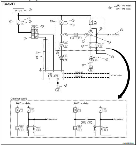
Description
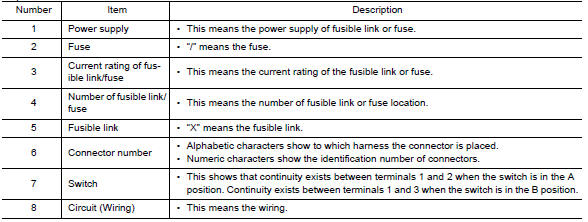
SWITCH POSITIONS
Switches are shown in wiring diagrams as if the vehicle is in the ŌĆ£normalŌĆØ condition.
A vehicle is in the ŌĆ£normalŌĆØ condition when: ŌĆó ignition switch is ŌĆ£OFFŌĆØ, ŌĆó doors, hood and trunk lid/back door are closed, ŌĆó pedals are not depressed, and ŌĆó parking brake is released.
MULTIPLE SWITCH
The continuity of multiple switch is described in two ways as shown below.
ŌĆó The switch chart is used in schematic diagrams.
ŌĆó The switch diagram is used in wiring diagrams.

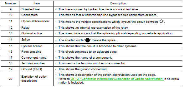
 Connector Symbols
Most of connector symbols in wiring diagrams are shown from the terminal
side.
ŌĆó Connector symbols shown from the terminal side are enclosed by
a single line and followed by the direction mark ...
 Connector Information/Explanation of Option Abbreviation
CONNECTOR LIST
Connector information and harness layout are described in ŌĆ£POWER SUPPLY,
GROUND & CIRCUIT ELEMENTSŌĆØ
Section.
EXPLANATION OF OPTION ABBREVIATION
HOW TO USE CONNECTOR IN ...
Other materials:
Parking brake control
Exploded View
2WD
1. Parking brake lever assembly
2. Adjusting nut
3. Parking brake switch
4. Front cable
5. Rear cable (LH)
6. Rear cable (RH)
: Apply multi-purpose grease.
: N┬Ęm (kg-m, ft-lb)
: N┬Ęm (kg-m, in-lb)
: Always replace after every
disassembly.
4WD
1. Parking brak ...
A/C unit assembly
Exploded View (Automatic Air Conditioning)
REMOVAL
LHD models (4WD)
1. A/C unit assembly
2. Drain hose
3. Steering member
4. Instrument stay
: Clip
: N┬Ęm (kg-m, ft-lb)
DISASSEMBLY
LHD models (4WD)
1. Ventilator seal
2. Defroster seal
3. Upper attachment case
4. Sub defroster d ...
Windows
POWER WINDOWS
WARNING
ŌĆó Make sure that all passengers have their hands, etc. inside the vehicle
while it is in motion and before closing the windows. Use the window lock switch
to prevent unexpected use of the power windows.
ŌĆó Do not leave children unattended inside the vehicle. They coul ...
