Nissan Juke Service and Repair Manual : B2623 inside antenna
DTC Logic
DTC DETECTION LOGIC
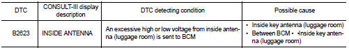
DTC CONFIRMATION PROCEDURE
1.PERFORM DTC CONFIRMATION PROCEDURE
1. Select “INTELLIGENT KEY” of “BCM” using CONSULT-III.
2. Select “INSIDE ANT DIAGNOSIS” in “WORK SUPPORT” mode.
3. Perform inside key antenna (“INSIDE ANT DIAGNOSIS”) on “WORK SUPPORT” of “INTELLIGENT KEY”.
4. Check BCM for DTC.
Is inside key antenna DTC detected? YES >> Refer to DLK-59, "Diagnosis Procedure".
NO >> Inside key antenna (luggage room) is OK.
Diagnosis Procedure
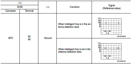
1.CHECK INSIDE KEY ANTENNA INPUT SIGNAL 1
1. Turn ignition switch ON.
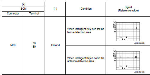
2. Check signal between BCM harness connector and ground using oscilloscope.
Is the inspection result normal? YES >> Replace BCM. Refer to BCS-93, "Removal and Installation".
NO >> GO TO 2.
2.CHECK INSIDE KEY ANTENNA CIRCUIT
1. Turn ignition switch OFF.
2. Disconnect BCM connector and inside key antenna (luggage room) connector.
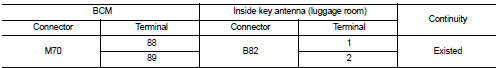
3. Check continuity between BCM harness connector and inside key antenna (luggage room) harness connector.
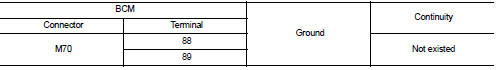
4. Check continuity between BCM harness connector and ground.
Is the inspection result normal? YES >> GO TO 3.
NO >> Repair or replace harness.
3.CHECK INSIDE KEY ANTENNA INPUT SIGNAL 2
1. Replace inside key antenna (luggage room). (New antenna or other
antenna)
2. Connect BCM connector and inside key antenna (luggage room) connector.
3. Turn ignition switch ON.
4. Check signal between BCM harness connector and ground using oscilloscope.
Is the inspection result normal? YES >> Replace inside key antenna (luggage room).
NO >> Replace BCM. Refer to BCS-93, "Removal and Installation".
 B2622 inside antenna
DTC Logic
DTC DETECTION LOGIC
DTC CONFIRMATION PROCEDURE
1.PERFORM DTC CONFIRMATION PROCEDURE
1. Select “INTELLIGENT KEY” of “BCM” using CONSULT-III.
2. Select “INSIDE ANT DIAGNOSIS†...
 B2626 outside antenna
DTC Logic
DTC DETECTION LOGIC
DTC CONFIRMATION PROCEDURE
1.PERFORM DTC CONFIRMATION PROCEDURE
1. Disconnect outside key antenna (driver side) connector.
2. Perform “INTELLIGENT KEY” Self Di ...
Other materials:
Small children
Children that are over 1 year old and weigh at least 20 lbs (9 kg) should remain
in a rear-facing child restraint as long as possible up to the height or weight
limit of the child restraint.
Children who outgrow the height or weight limit of the rear-facing child restraint
and are at least 1 ...
Blower fan resistor
Exploded View
1. A/C unit assembly
2. Fan control amp.*1
3. Blower fan resistor*2
4. Blower motor
5. Blower motor cover
• *1: Automatic air conditioner
• *2: Manual air conditioner
Removal and Installation
REMOVAL
1. Remove instrument panel assembly. Refer to IP-13, "Removal ...
A/C on signal
Component Function Check
1.CHECK A/C ON SIGNAL
With CONSULT-III
1. Turn ignition switch ON.
2. Operate blower motor.
3. Select “AIR CONDITIONER” of “BCM” using CONSULT-III.
4. Select “AIR COND SW” in “DATA MONITOR” mode.
5. Check A/C ON signal when the A/C switch is operated.
...
