Nissan Juke Service and Repair Manual : B2626 outside antenna
DTC Logic
DTC DETECTION LOGIC
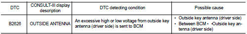
DTC CONFIRMATION PROCEDURE
1.PERFORM DTC CONFIRMATION PROCEDURE
1. Disconnect outside key antenna (driver side) connector.
2. Perform ÔÇťINTELLIGENT KEYÔÇŁ Self Diagnostic Result.
Is outside key antenna DTC detected? YES >> Refer to DLK-61, "Diagnosis Procedure".
NO >> Outside key antenna (driver side) is OK.
Diagnosis Procedure
1.CHECK OUTSIDE KEY ANTENNA INPUT SIGNAL 1
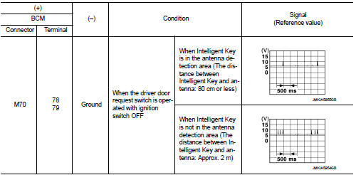
1. Turn ignition switch OFF.
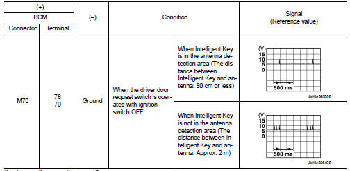
2. Check signal between BCM harness connector and ground using oscilloscope.
Is the inspection result normal? YES >> Replace BCM. Refer to BCS-93, "Removal and Installation".
NO >> GO TO 2.
2.CHECK OUTSIDE KEY ANTENNA CIRCUIT
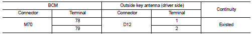
1. Disconnect BCM connector and outside key antenna (driver side) connector.
2. Check continuity between BCM harness connector and outside key antenna (driver side) harness connector.
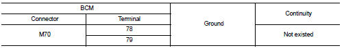
3. Check continuity between BCM harness connector and ground.
Is the inspection result normal? YES >> GO TO 3.
NO >> Repair or replace harness.
3.CHECK OUTSIDE KEY ANTENNA INPUT SIGNAL 2
1. Replace outside key antenna (driver side). (New antenna or other
antenna)
2. Connect BCM connector and outside key antenna (driver side) connector.
3. Check signal between BCM harness connector and ground using oscilloscope.
Is the inspection result normal? YES >> Replace outside key antenna (driver side).
NO >> Replace BCM. Refer to BCS-93, "Removal and Installation".
 B2623 inside antenna
DTC Logic
DTC DETECTION LOGIC
DTC CONFIRMATION PROCEDURE
1.PERFORM DTC CONFIRMATION PROCEDURE
1. Select ÔÇťINTELLIGENT KEYÔÇŁ of ÔÇťBCMÔÇŁ using CONSULT-III.
2. Select ÔÇťINSIDE ANT DIAGNOSISÔÇ ...
 B2627 outside antenna
DTC Logic
DTC DETECTION LOGIC
DTC CONFIRMATION PROCEDURE
1.PERFORM DTC CONFIRMATION PROCEDURE
1. Disconnect outside key antenna (passenger side) connector.
2. Perform ÔÇťINTELLIGENT KEYÔÇŁ Self ...
Other materials:
Oil pump
Exploded View
1. Oil pump drive chain
2. Crankshaft sprocket
3. Oil pump assembly
Removal and Installation
REMOVAL
1. Disconnect the battery cable from the negative terminal.
2. Remove engine under cover.
3. Remove front wheel RH. Refer to WT-7, "Exploded View".
4. Remove fen ...
Seat belt buckle switch signal circuit (driver side)
Component Function Check
1.CHECK COMBINATION METER INPUT SIGNAL
Select the ÔÇťData MonitorÔÇŁ for the ÔÇťMETER/M&AÔÇŁ and check the ÔÇťBUCKLE SWÔÇŁ
monitor value.
BUCKLE SW
When driver seat belt is fastened : Off
When driver seat belt is unfastened : On
>> INSPECTION END
Diagnosis ...
Input shaft and gear
Exploded View
1. Input shaft front bearing
2. Input shaft
3. Snap ring
4. Input shaft rear bearing
5. Adapter plate
6. Bushing
7. 5th input gear
8. 5th-reverse baulk ring
9. Synchronizer lever
10. 5th-reverse synchronizer hub
11. 5th-reverse coupling sleeve
12. Retaining pin
1 ...
