Nissan Juke Service and Repair Manual : Oil pump
Exploded View
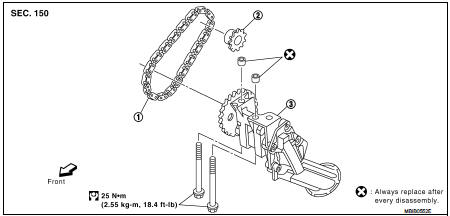
1. Oil pump drive chain
2. Crankshaft sprocket
3. Oil pump assembly
Removal and Installation
REMOVAL
1. Disconnect the battery cable from the negative terminal.
2. Remove engine under cover.
3. Remove front wheel RH. Refer to WT-7, "Exploded View".
4. Remove fender protector RH. Refer to EXT-22, "Exploded View".
5. Remove drive belt. Refer to EM-276, "Removal and Installation".
6. Remove oil pan. Refer to EM-288, "Exploded View".
7. Remove rear oil seal retainer. Refer to EM-302, "Exploded View".
8. Remove oil pump drive chain. Refer to EM-330, "Disassembly and Assembly".
9. Remove oil pump assembly.
INSTALLATION
Install in the reverse order of removal paying attention to the following.
Rear Oil Seal Retainer and Oil Pump • Refer to EM-330, "Disassembly and Assembly".

 Oil cooler
Exploded View
1. Cylinder block
2. Water pipe
3. O-ring
4. O-ring
5. O-ring
6. Oil cooler
7. Connecting stud
8. O-ring
9. Oil filter bracket
10. Oil pressure switch
11. Oil filter ...
Other materials:
Push-button ignition switch positions
LOCK (Normal parking position)
The ignition switch can only be locked in this position.
The ignition switch will be unlocked when it is pushed to the ACC position while
carrying the Intelligent Key.
ACC (Accessories)
This position activates electrical accessories such as the radio, when the en ...
Service data and specifications (SDS)
SERVICE DATA AND SPECIFICATIONS (SDS)
Idle Speed
*: Under the following conditions
• A/C switch: OFF
• Electric load: OFF (Lights, heater fan & rear window defogger)
• Steering wheel: Kept in straight-ahead position
Ignition Timing
*: Under the following conditions
• A/C swit ...
Appearance and care
Removing spots
To preserve the pristine finish of your Nissan Leaf, it is essential to remove stubborn contaminants such as road tar, oil splatters, industrial fallout, insect residue, and tree sap as promptly as possible. If left to sit, these substances can chemically bond with or etch the pa ...
