Nissan Juke Service and Repair Manual : Oil cooler
Exploded View
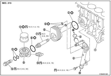
1. Cylinder block
2. Water pipe
3. O-ring
4. O-ring
5. O-ring
6. Oil cooler
7. Connecting stud
8. O-ring
9. Oil filter bracket
10. Oil pressure switch
11. Oil filter
12. O-ring
13. Connecting bolt
A. : To radiator lower hose B. : To water pump
 : N·m (kg-m, ft-lb)
 : Always replace after every
disassembly.
CAUTION:
• Be careful not to get burned when the engine and engine oil are hot.
• When removing, prepare a shop cloth to absorb any oil leakage or spillage.
• Completely wipe off any oil that abhere to the engine and the vehicle.
Removal and Installation
REMOVAL
1. Drain engine coolant. Refer to CO-62, "Draining".
CAUTION:
Perform when engine is cold.
2. Remove oil filter and oil filter bracket. Refer to LU-35, "Exploded View".
3. Remove alternator.
4. Remove oil cooler.
INSTALLATION
Installation is in reverse order of removal.
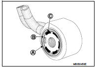
• Replace the O-ring (A) of the oil cooler, positioning the lip (B) of the seal behind the lug (C) of the oil cooler.
• Confirm that no foreign objects are adhering to the installation planes of the oil cooler and block.
Inspection
Oil Cooler
Check oil cooler for cracks and clogging by blowing through coolant inlet. If
necessary, replace oil cooler
assembly.
 Oil pump
Exploded View
1. Oil pump drive chain
2. Crankshaft sprocket
3. Oil pump assembly
Removal and Installation
REMOVAL
1. Disconnect the battery cable from the negative terminal.
2. Remove eng ...
 Service data and specifications
(SDS)
Service data and specifications
(SDS)
Standard and Limit
OIL PRESSURE
OIL CAPACITY (APPROXIMATE)
TIGHTENING TORQUE
...
Other materials:
Glow plug
Exploded View
1. Glow plug
Engine front
: N·m (kg-m, ft-lb)
Removal and Installation
REMOVAL
CAUTION:
Remove glow plug only if necessary. If carbon adheres, it may be stuck and
broken.
1. Disconnect the battery cable from the negative terminal.
2. Remove cowl top extension. Refer to E ...
CAN communication circuit
Description
CAN (Controller Area Network) is a serial communication line for real time
application. It is an on-vehicle multiplex
communication line with high data communication speed and excellent error
detection ability. Many electronic
control units are equipped onto a vehicle, and each co ...
CVT fluid
Inspection
CHECKING CVT FLUID
The fluid level should be checked with the fluid warmed up to 50 to 80°C (122
to 176°F). The fluid level check
procedure is as follows:
1. Check for fluid leakage.
2. With the engine warmed up, drive the vehicle in an urban area.
When ambient temperature is ...
