Nissan Juke Service and Repair Manual : Input shaft and gear
Exploded View
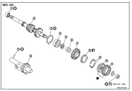
1. Input shaft front bearing
2. Input shaft
3. Snap ring
4. Input shaft rear bearing
5. Adapter plate
6. Bushing
7. 5th input gear
8. 5th-reverse baulk ring
9. Synchronizer lever
10. 5th-reverse synchronizer hub
11. 5th-reverse coupling sleeve
12. Retaining pin
13. Reverse gear
 : Apply gear oil.
 : Replace the parts as a set.
 : Always replace after every
disassembly.
 : N·m (kg-m, ft-lb)
Disassembly
Refer to TM-37, "Disassembly" for disassembly procedure.
Assembly
Refer to TM-43, "Assembly" for assembly procedure.
Inspection
INSPECTION AFTER DISASSEMBLY
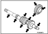
Input Shaft and Gear
Check the following items and replace if necessary.
• Damage, peeling, bend, uneven wear, and distortion of shaft.
• Excessive wear, damage, and peeling of gear.
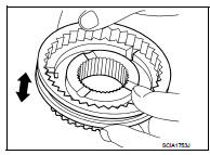
Synchronizer Hub and Coupling Sleeve Check the following items and replace if necessary.
• Breakage, damage, and unusual wear on contact surface of coupling sleeve, synchronizer hub, and insert key.
• Coupling sleeve and synchronizer hub move smoothly.
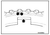
Baulk RingBaulk Ring Check contact surface of baulk ring cam and insert key for excessive wear, uneven wear, bend, and damage. Replace if necessary.
Check contact surface of baulk ring cam and insert key for excessive wear, uneven wear, bend, and damage. Replace if necessary.
Bearing
Check bearing for damage and unsmooth rotation. Replace if necessary.
 Transaxle assembly
Exploded View
CASE AND HOUSING
1. Differential side oil seal
2. Clutch housing
3. 2 way connector
4. Oil gutter
5. Air breather inner tube
6. Filler plug
7. Gasket
8. Transaxle case
9 ...
 Mainshaft and gear
Exploded View
1. Mainshaft front bearing outer
race
2. Mainshaft front bearing inner race
3. Mainshaft
4. 1st main gear
5. 1st inner baulk ring
6. 1st synchronizer cone
7. 1st outer baulk ...
Other materials:
Diagnosis system (BCM)
Common item
COMMON ITEM : CONSULT-III Function (BCM - COMMON ITEM)
APPLICATION ITEM
CONSULT-III performs the following functions via CAN communication with BCM.
SYSTEM APPLICATION
BCM can perform the following functions for each system.
NOTE:
It can perform the diagnosis modes except the ...
B1185 lap Pre-tensioner LH
DTC Logic
DTC CONFIRMATION PROCEDURE
1.CHECK SELF-DIAGNOSTIC RESULT
With CONSULT-III
1. Turn ignition switch ON.
2. Perform “Self Diagnostic Result” mode of “AIR BAG” using CONSULT-III.
Without CONSULT-III
1. Turn ignition switch ON.
2. Check the air bag warning lamp status. Refe ...
Anti-lock Braking System (ABS)
WARNING
While the Anti-lock Braking System (ABS) is a highly advanced safety feature, it cannot override the laws of physics or compensate for reckless and dangerous driving. The primary role of the ABS is to help the driver maintain steering control and vehicle stability during hard ...
