Nissan Juke Service and Repair Manual : Component parts
Component Parts Location
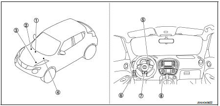
1. A/C auto amp.
Refer to HAC-12, "Component Parts Location".
2. ABS actuator and electric unit (control unit) Refer to BRC-9, "Component Parts Location" (without ESP) or BRC-97, "Component Parts Location" (with ESP).
3. ECM Refer to EC-25, "ENGINE CONTROL SYSTEM : Component Parts Location" (MR16DDT), EC-455, "ENGINE CONTROL SYSTEM : Component Parts Location" (HR16DE) or EC-813, "Component Parts Location" (K9K).
4. TCM Refer to TM-314, "CVT CONTROL SYSTEM : Component Parts Location" (CVT: RE0F11A) or TM-131, "CVT CONTROL SYSTEM : Component Parts Location" (CVT RE0F10A).
5. Combination meter
6. BCM
Refer to BCS-6, "BODY CONTROL
SYSTEM : Component Parts Location"
(with Intelligent Key system) or
BCS-96, "BODY CONTROL SYSTEM
: Component Parts Location"
(without Intelligent Key system).
7. EPS control unit Refer to STC-5, "Component Parts Location".
8. Multi display unit
Component Description
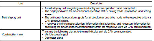
Multi Display Unit
• A multi display unit integrating a color display and an operation panel is adopted.
• It is connected to other units via CAN communication and performs the drive mode control, air conditioner control, display of various information, and various settings.
• The display can show the drive mode (NORMAL, SPORT, ECO), drive information (travel time, mileage, average vehicle speed), ECO information (fuel consumption history), setting screen as well as engine power, providing information on the vehicle status according to the driver's operation.
• For the operation switch section, newly developed unique switches are adopted, which respectively have 2 types of symbols and functions.
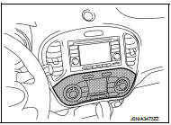
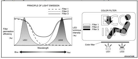
UNIQUE SWITCH
The switch integrates 2 types of LEDs*, filters that pass or absorb specified wavelengths (filter 1, filter 2), and filters adapted to both display colors (filter 3), enabling 2 different symbols to be displayed at a same position by LED changeover.
*: Abbreviation of light emitting diode. It is a semiconductor device that lights up when electric current is applied.
Operation description of unique switch
In drive mode
• LED1 lights up, the light from LED1 passes filter 1 and filter 3, and “ECO
INFO” is displayed.
In air conditioner mode
• LED2 lights up, the light from LED2 passes filter 2 and filter 3, and “
” is displayed.

 System
NISSAN dynamic control system
NISSAN DYNAMIC CONTROL SYSTEM : System Description
SYSTEM DIAGRAM
• *1: M/T models except for K9K engine models
• *2: CVT models
MULTI DISPLAY UNIT INPUT/OUTPU ...
Other materials:
P1811 power supply circuit for 4wd control module
DTC Logic
DTC DETECTION LOGIC
DTC CONFIRMATION PROCEDURE
1.PRECONDITIONING
If “DTC CONFIRMATION PROCEDURE” has been previously conducted, always turn
ignition switch OFF and
wait at least 10 seconds before conducting the next test.
>> GO TO 2.
2.DTC REPRODUCTION PROCEDURE
W ...
Foreword
This manual contains maintenance and repair procedures for the NISSAN
JUKE, model F15 series.
In order to assure your safety and the efficient functioning of the vehicle,
this manual should be read thoroughly. It is especially important that the
PRECAUTIONS in the GI section be completely unde ...
System (intelligent key system)
Intelligent key system
INTELLIGENT KEY SYSTEM : System Diagram
INTELLIGENT KEY SYSTEM : System Description
• The Intelligent Key system is a system that makes it possible to lock and
unlock the door locks (door lock/
unlock function) by carrying the Intelligent Key, which operates based on ...
