Nissan Juke Service and Repair Manual : ASCD brake switch
Component Function Check
1.CHECK ASCD BRAKE SWITCH FUNCTION
 With CONSULT-III
1. Turn ignition switch ON.
2. Select ŌĆ£ENGINEŌĆØ using CONSULT-III.
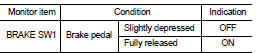
3. Select ŌĆ£BRAKE SW1ŌĆØ in ŌĆ£DATA MONITORŌĆØ mode.
4. Check ŌĆ£BRAKE SW1ŌĆØ indication under the following conditions.
 Without CONSULT-III
1. Turn ignition switch ON.
2. Check the voltage between ECM harness connector terminals under the following conditions.
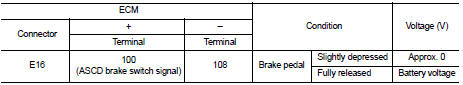
Is the inspection result normal? YES >> INSPECTION END
NO >> Go to EC-765, "Diagnosis Procedure".
Diagnosis Procedure
1.CHECK ASCD BRAKE SWITCH POWER SUPPLY CIRCUIT
1. Turn ignition switch OFF.
2. Disconnect ASCD brake switch harness connector.
3. Turn ignition switch ON.
4. Check the voltage between ASCD brake switch harness connector and ground.
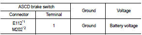
*1: LHD models or RHD models with CVT *2: RHD models with M/T
Is the inspection result normal? YES >> GO TO 3.
NO >> GO TO 2.
2.DETECT MALFUNCTIONING PART
Check the following.
ŌĆó Harness connector E105, M77 (LHD models or RHD models with CVT)
ŌĆó Harness connector M84, M201 (RHD models with M/T)
ŌĆó 10A fuse (No. 3)
ŌĆó Harness for open or short between ASCD brake switch and fuse
>> Repair open circuit or short to ground in harness or connectors.
3.CHECK ASCD BRAKE SWITCH INPUT SIGNAL CIRCUIT FOR OPEN AND SHORT
1. Turn ignition switch OFF.
2. Disconnect ECM harness connector.
3. Check the continuity between ASCD brake switch harness connector and ECM harness connector.
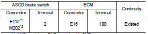
*1: LHD models or RHD models with CVT *2: RHD models with M/T
4. Also check harness for short to ground and short to power.
Is the inspection result normal? YES >> GO TO 4.
NO >> Harness for open or short between ECM and ASCD brake switch 4.CHECK ASCD BRAKE SWITCH
Refer to EC-766, "Component Inspection (ASCD Brake Switch)" Is the inspection result normal? YES >> GO TO 5.
NO >> Replace ASCD brake switch.
5.CHECK INTERMITTENT INCIDENT
Refer to GI-42, "Intermittent Incident".
>> INSPECTION END
Component Inspection (ASCD Brake Switch)
1.CHECK ASCD BRAKE SWITCH-I
1. Turn ignition switch OFF.
2. Disconnect ASCD brake switch harness connector.
3. Check the continuity between ASCD brake switch terminals under the following conditions.
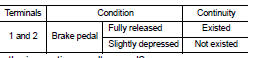
Is the inspection result normal? YES >> INSPECTION END
NO >> GO TO 2.
2.CHECK ASCD BRAKE SWITCH-II
1. Adjust ASCD brake switch installation. Refer to BR-22, "Inspection and Adjustment" (LHD) or BR-90, "Inspection and Adjustment" (RHD).
2. Check the continuity between ASCD brake switch terminals under the following conditions.
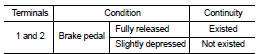
Is the inspection result normal? YES >> INSPECTION END
NO >> Replace ASCD brake switch. Refer to BR-88, "Exploded View".
 P2A00 A/F sensor 1
DTC Logic
DTC DETECTION LOGIC
To judge the malfunction, the A/F signal computed by ECM from the A/F sensor
1 signal is monitored so it will
not shift to LEAN side or RICH side.
DTC CONFIRMATIO ...
 ASCD indicator
Component Function Check
1.CHECK ASCD INDICATOR FUNCTION
Check ASCD indicator under the following conditions.
Is the inspection result normal?
YES >> INSPECTION END
NO >> Go to EC-7 ...
Other materials:
Valve oil seal
VALVE OIL SEAL : Removal and Installation
REMOVAL
1. Remove camshafts. Refer to EM-78, "Exploded View".
2. Remove valve lifters. Refer to EM-78, "Exploded View".
3. Rotate crankshaft, and set piston whose valve oil seal is to be removed to
TDC. This will prevent valve
from ...
Basic inspection
DIAGNOSIS AND REPAIR WORKFLOW
Work Flow
OVERALL SEQUENCE
DETAILED FLOW
1.OBTAIN INFORMATION ABOUT SYMPTOM
Interview the customer to obtain as much information as possible about the
conditions and environment under
which the malfunction occurred.
>> GO TO 2.
2.CHECK SYMPTOM
ŌĆó ...
Vehicle recovery (freeing a stuck vehicle)
WARNING
ŌĆó Stand clear of a stuck vehicle.
ŌĆó Do not spin your tires at high speed.
This could cause them to explode and result in serious injury. Parts of your
vehicle could also overheat and be damaged.
Pulling a stuck vehicle
Do not use the tie down hook for towing or vehicle recov ...
