Nissan Juke Service and Repair Manual : Drive belt
Exploded View
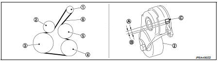
1. Alternator
2. Drive belt auto-tensioner
3. Crankshaft pulley
4. A/C compressor
5. Water pump
6. Drive belt
A. Possible use range B.
Range when new drive belt is installed C. Indicator
Checking
WARNING
: Perform this step when engine is stopped.
• Check that the indicator (C) (notch on fixed side) of drive belt auto-tensioner is within the possible use range (A) in the figure.
NOTE
:
• Check the drive belt auto-tensioner indication when the engine is cold.
• When new drive belt is installed, the indicator (notch on fixed side) should be within the range (B) in the figure.
• Visually check entire drive belt for wear, damage or cracks.
• If the indicator (notch on fixed side) is out of the possible use range or belt is damaged, replace drive belt.
Tension Adjustment
Refer to : EM-129, "Drive Belt".
Removal and Installation
REMOVAL
1. Turn the steering wheel to the right.
2. Remove the front fender protector (RH) front side bolts and clips. And keep a service area. Refer to EXT- 22, "Exploded View".
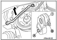
3. Hold the hexagonal part (A) of drive belt auto-tensioner (1) with a wrench securely. Then move the wrench handle in the direction of arrow (loosening direction of tensioner).
CAUTION
:
Avoid placing hand in a location where pinching may occur if the holding tool accidentally comes off
.
4. Insert a rod approximately 6 mm (0.24 in) in diameter such as short-length screwdriver into the hole (B) of the retaining boss to fix drive belt auto-tensioner.
• Keep drive belt auto-tensioner pulley arm locked after drive belt is removed.
5. Remove drive belt.
INSTALLATION
1. Install drive belt.
CAUTION
:
• Confirm drive belt is completely set to pulleys.
• Check for engine oil, working fluid and engine coolant are not adhered to drive belt and each pulley groove
.
2. Release drive belt auto-tensioner, and apply tension to drive belt.
3. Turn crankshaft pulley clockwise several times to equalize tension between each pulley.
4. Confirm tension of drive belt at indicator (notch on fixed side) is within the possible use range. Refer to EM-20, "Exploded View".

 Air cleaner filter
Removal and Installation
REMOVAL
1. Remove air duct assembly (duct side) (1).
2. Unhook the tabs (A) of both ends of the air cleaner cover.
3. Remove the air cleaner filter (1) and air cleaner b ...
Other materials:
System initialization
Description
If any of the following operations are performed, the initialization is
necessary for normal operation of power
window system.
• Disconnection and connection of battery cable from negative terminal.
• When power window main switch replaced.
• Electric power supply to power ...
Precaution Necessary for Steering Wheel Rotation after Battery Disconnect
NOTE:
• Before removing and installing any control units, first turn the ignition
switch to the LOCK position, then disconnect
both battery cables.
• After finishing work, confirm that all control unit connectors are connected
properly, then re-connect both
battery cables.
• Always us ...
Service Notice or Precautions for Manual Transaxle
CAUTION:
• Never reuse CSC (Concentric Slave Cylinder). Because CSC slides back to the
original position
every time when removing transaxle assembly. At this timing, dust on the sliding
parts may damage
a seal of CSC and may cause clutch fluid leakage. Refer to CL-27, "Removal and
In ...
