Nissan Juke Service and Repair Manual : Diagnosis system (EPS control unit)
Consult-III Function
FUNCTION
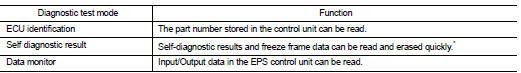
CONSULT-III can display each diagnostic item using the diagnostic test modes shown following.
*: The following diagnosis information is erased by erasing.
ŌĆó DTC
ŌĆó Freeze frame data (FFD)
ECU IDENTIFICATION
Displays the part number stored in the control unit.
SELF-DIAG RESULTS MODE
Refer to STC-14, "DTC Index".
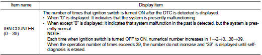
When ŌĆ£CRNTŌĆØ is displayed on self-diagnosis result.
ŌĆó The system is presently malfunctioning.
When ŌĆ£PASTŌĆØ is displayed on self-diagnosis result.
ŌĆó System malfunction in the past is detected, but the system is presently normal.
FREEZE FRAME DATA (FFD)
The following vehicle status is recorded when DTC is detected and is displayed on CONSULT-III.
DATA MONITOR MODE
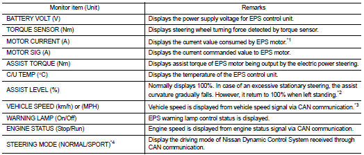
*1: Almost in accordance with the value of ŌĆ£MOTOR SIGŌĆØ. It is not a malfunction though these values are not accorded when steering quickly.
*2: Normally displays 100%. In case of an excessive stationary steering, the assist curvature gradually falls. However, it returns to 100% when left standing.
*3: It is not a malfunction, though it might not be corresponding just after ignition switch in turned ON.
*4: Displays NORMAL in models without Nissan Dynamic Control System.
 System
EPS system : System Description
ŌĆó EPS control unit performs an arithmetical operation on data, such
as steering wheel turning force (sensor signal) from the torque
sensor, vehicle speed signal, e ...
 ECU diagnosis information
EPS control unit
Reference Value
VALUES ON THE DIAGNOSIS TOOL
CAUTION:
The output signal indicates the EPS control unit calculation data. The normal
values will be displayed
even in the event t ...
Other materials:
Precautions for Harness Repair
ŌĆó Solder the repaired area and wrap tape around the soldered area.
NOTE:
A fray of twisted lines must be within 110 mm (4.33 in).
ŌĆó Bypass connection is never allowed at the repaired area.
NOTE:
Bypass connection may cause CAN communication error. The
spliced wire becomes separated a ...
Squeak and rattle trouble diagnoses
Work Flow
CUSTOMER INTERVIEW
Interview the customer if possible, to determine the conditions that exist
when the noise occurs. Use the Diagnostic
Worksheet during the interview to document the facts and conditions when the
noise occurs and any of
the customer's comments; refer to MIR-39, & ...
Intelligent Key
Replace the battery in the Intelligent Key as follows: 1. Remove the mechanical
key from the Intelligent Key.
2. Insert a small screwdriver into the slit of the corner and twist it to separate
the upper part from the lower part. Use a cloth to protect the casing.
3. Replace the battery with ...
