Nissan Juke Service and Repair Manual : System
EPS system : System Description
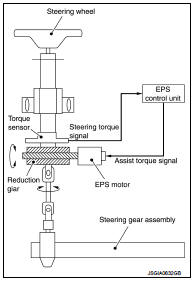
• EPS control unit performs an arithmetical operation on data, such as steering wheel turning force (sensor signal) from the torque sensor, vehicle speed signal, etc. Then it generates an optimum assist torque signal to the EPS motor according to the driving condition.
• In case of an error in the electrical system, the fail-safe function stops output signals to the EPS motor. Refer to STC-9, "EPS SYSTEM : Fail-Safe".
• EPS control unit decreases the output signal to EPS motor while extremely using the power steering function (e.g., full steering) consecutively for protecting EPS motor and EPS control unit (Overload protection control). Refer to STC-9, "EPS SYSTEM : Protection Function".
• EPS control unit will decrease assistance under the following 2 conditions.
- Extensive steering at low speed will cause the EPS control unit and EPS motor to heat up, once temperature reaches critical point EPS control unit will reduce current to reduce heat up. System will recover as temperature lowers (reduced or no assistance).
- Holding steering on rack-end (full lock) for 1 second will cause the system to engage rack-end protection. This reduces assistance down to 50% in order to prevent heat up. Assistance is immediately returned to 100% when steering released or turned away from rack-end.
• In SPORT mode, changes the steering assist characteristic to enhance a stable steering feel according to the mode signals from multi display unit via CAN communication. (Models with Nissan Dynamic Control System)
SYSTEM DIAGRAM
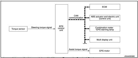
Multi display unit is applied to models with Nissan Dynamic Control System.
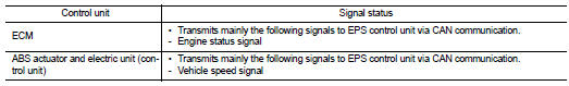
INPUT/OUTPUT SIGNAL
Communicates the signal from each control unit via CAN communication.
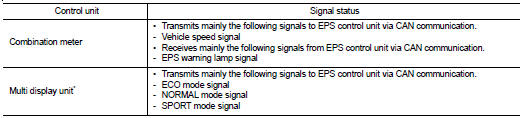
*: Models with Nissan Dynamic Control System
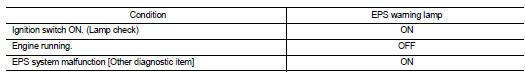
EPS WARNING LAMP INDICATION
• Turn ON when there is a malfunction in EPS system. If indicates that fail-safe mode is engaged and enters a manual steering state (Control turning force steering wheel becomes heavy).
• Also turns ON when ignition switch is turned ON, for purpose of lamp check. Turns OFF after the engine starts, if system is normal.
CAUTION:
EPS warning lamp also turns ON due to data reception error, CAN communication
error etc.
EPS system : Fail-Safe
• If any malfunction occurs in the system, and control unit detects the malfunction, EPS warning lamp on combination meter turns ON to indicate system malfunction.
• When EPS warning lamp is ON, enters into a manual steering state. (Control turning force steering wheel becomes heavy.)
EPS system : Protection Function
EPS control unit decreases the output signal to EPS motor while extremely using the power steering function (e.g., full steering) consecutively for protecting EPS motor and EPS control unit (Overload protection control).
While activating overload protection control, the assist torque gradually decreases, and the steering wheel turning force becomes heavy. The normal assist torque is recovered if the steering wheel is not turned for a while.
 Component parts
Component Parts Location
LHD models
1. Multi display unit*
Refer to DMS-3, "Component Parts
Location".
2. ABS actuator and electric unit (control
unit)
Refer to BRC-9, "Compone ...
 Diagnosis system (EPS control unit)
Consult-III Function
FUNCTION
CONSULT-III can display each diagnostic item using the diagnostic test modes
shown following.
*: The following diagnosis information is erased by erasing.
• DTC ...
Other materials:
C1101, C1102, C1103, C1104 WHEEL SENSOR
DTC Logic
DTC DETECTION LOGIC
DTC CONFIRMATION PROCEDURE
1.PRECONDITIONING
If “DTC CONFIRMATION PROCEDURE” has been previously conducted, always turn
ignition switch OFF and
wait at least 10 seconds before conducting the next test.
>> GO TO 2.
2.CHECK DTC DETECTION
With CON ...
Additional service when replacing control unit
ECM
ECM : Description
Performing the following procedure can automatically activate recommunication
of ECM and BCM, but only
when the ECM is replaced with a new one*.
*: New one means a virgin ECM that has never been energized on-board.
(In this step, initialization procedure by CONSULT-I ...
License plate lamp
Exploded View
1. License plate lamp housing assembly
2. Blub
3. License plate lamp blub socket
: Pawl
Removal and Installation
CAUTION:
Disconnect battery negative terminal or remove the fuse.
REMOVAL
1. While pressing the license plate lamp to direction right side, pull
it to directio ...
