Nissan Juke Service and Repair Manual : C1101, C1102, C1103, C1104 WHEEL SENSOR
DTC Logic
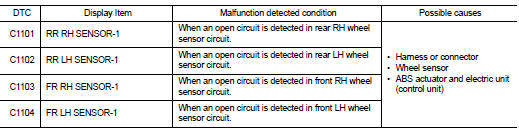
DTC DETECTION LOGIC
DTC CONFIRMATION PROCEDURE
1.PRECONDITIONING
If “DTC CONFIRMATION PROCEDURE” has been previously conducted, always turn ignition switch OFF and wait at least 10 seconds before conducting the next test.
>> GO TO 2.
2.CHECK DTC DETECTION
 With CONSULT-III.
1. Stat the engine.
2. Drive the vehicle at approx. 30 km/h (19 MPH) or more for approx. 1 minute.
3. Stop the vehicle.
4. Perform self-diagnosis for “ABS”.
Is DTC “C1101”, “C1102”, “C1103” or “C1104” detected? YES >> Proceed to BRC-36, "Diagnosis Procedure".
NO >> INSPECTION END
Diagnosis Procedure
CAUTION:
Never check between wheel sensor harness connector terminals.
1.CHECK WHEEL SENSOR
1. Turn the ignition switch OFF.
2. Check wheel sensor for damage.
Is the inspection result normal? YES >> GO TO 3.
NO >> GO TO 2.
2.REPLACE WHEEL SENSOR (1)
 With CONSULT-III.
1. Replace wheel sensor.
- Front: Refer to BRC-84, "FRONT WHEEL SENSOR : Removal and Installation".
- Rear: Refer to BRC-86, "REAR WHEEL SENSOR : Removal and Installation".
2. Erase Self-diagnosis result for “ABS”.
3. Turn the ignition switch OFF, and wait 10 seconds or more.
4. Stat the engine.
5. Drive the vehicle at approx. 30 km/h (19 MPH) or more for approx. 1 minute.
6. Stop the vehicle.
7. Perform self-diagnosis for “ABS”.
Is DTC “C1101”, “C1102”, “C1103” or “C1104” detected? YES >> GO TO 3.
NO >> INSPECTION END
3.CHECK CONNECTOR
1. Turn the ignition switch OFF.
2. Check ABS actuator and electric unit (control unit) harness connector for disconnection or looseness.
3. Check wheel sensor harness connector for disconnection or looseness.
Is the inspection result normal? YES >> GO TO 5.
NO >> Repair or replace error-detected parts, securely lock the connector, and GO TO 4.
4.PERFORM SELF-DIAGNOSIS (1)
 With CONSULT-III.
1. Erase Self-diagnosis result for “ABS”.
2. Turn the ignition switch OFF, and wait 10 seconds or more.
3. Stat the engine.
4. Drive the vehicle at approx. 30 km/h (19 MPH) or more for approx. 1 minute.
5. Stop the vehicle.
6. Perform self-diagnosis for “ABS”.
Is DTC “C1101”, “C1102”, “C1103” or “C1104” detected? YES >> GO TO 5.
NO >> INSPECTION END
5.CHECK TERMINAL
1. Turn the ignition switch OFF.
2. Disconnect ABS actuator and electric unit (control unit) harness connector and then check ABS actuator and electric unit (control unit) pin terminals for damage or loose connection with harness connector.
3. Disconnect wheel sensor harness connector and check each wheel sensor pin terminals for damage or loose connection with harness connector.
Is the inspection result normal? YES >> GO TO 7.
NO >> Repair or replace error-detected parts and GO TO 6.
6.PERFORM SELF-DIAGNOSIS (2)
 With CONSULT-III.
1. Connect ABS actuator and electric unit (control unit) harness connector.
2. Connect wheel sensor harness connector.
3. Erase Self-diagnosis result for “ABS”.
4. Turn the ignition switch OFF, and wait 10 seconds or more.
5. Stat the engine.
6. Drive the vehicle at approx. 30 km/h (19 MPH) or more for approx. 1 minute.
7. Stop the vehicle.
8. Perform self-diagnosis for “ABS”.
Is DTC “C1101”, “C1102”, “C1103” or “C1104” detected? YES >> GO TO 7.
NO >> INSPECTION END
7.CHECK WHEEL SENSOR HARNESS
1. Turn the ignition switch OFF.
2. Disconnect ABS actuator and electric unit (control unit) harness connector.
3. Disconnect wheel sensor harness connector.
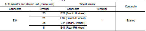
4. Check continuity between ABS actuator and electric unit (control unit) harness connector and wheel sensor harness connector. (Check continuity when steering wheel is steered to RH and LH, or center harness in wheel housing is moved.)
Measurement connector and terminal for power supply circuit
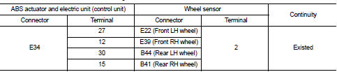
Measurement connector and terminal for signal circuit
Is the inspection result normal? YES >> GO TO 9.
NO >> Repair or replace error-detected parts and GO TO 8.
8.PERFORM SELF-DIAGNOSIS (3)
With CONSULT-III.
1. Connect ABS actuator and electric unit (control unit) harness connector.
2. Connect wheel sensor harness connector.
3. Erase Self-diagnosis result for “ABS”.
4. Turn the ignition switch OFF, and wait 10 seconds or more.
5. Stat the engine.
6. Drive the vehicle at approx. 30 km/h (19 MPH) or more for approx. 1 minute.
7. Stop the vehicle.
8. Perform self-diagnosis for “ABS”.
Is DTC “C1101”, “C1102”, “C1103” or “C1104” detected? YES >> GO TO 9.
NO >> INSPECTION END
9.REPLACE WHEEL SENSOR
With CONSULT-III.
1. Replace wheel sensor.
- Front: Refer to BRC-84, "FRONT WHEEL SENSOR : Removal and Installation".
- Rear: Refer to BRC-86, "REAR WHEEL SENSOR : Removal and Installation".
2. Erase Self-diagnosis result for “ABS”.
3. Turn the ignition switch OFF, and wait 10 seconds or more.
4. Stat the engine.
5. Drive the vehicle at approx. 30 km/h (19 MPH) or more for approx. 1 minute.
6. Stop the vehicle.
7. Perform self-diagnosis for “ABS”.
Is DTC “C1101”, “C1102”, “C1103” or “C1104” detected? YES >> Replace ABS actuator and electric unit (control unit). Refer to BRC-90, "Removal and Installation".
NO >> INSPECTION END

 C1105, C1106, C1107, C1108 wheel sensor
DTC Logic
DTC DETECTION LOGIC
DTC CONFIRMATION PROCEDURE
1.PRECONDITIONING
If “DTC CONFIRMATION PROCEDURE” has been previously conducted, always turn
ignition switch OFF and
wait at least ...
Other materials:
Interior room lamp control system
Wiring Diagram
For connector terminal arrangements, harness layouts, and alphabets in a
(option abbreviation: if not
described in wiring diagram), refer to GI-12, "Connector Information/Explanation
of Option Abbreviation".
...
C1604 torque sensor
DTC Logic
DTC DETECTION LOGI
DTC CONFIRMATION PROCEDURE
1.PRECONDITIONING
If “DTC CONFIRMATION PROCEDURE” has been previously conducted, always turn
ignition switch OFF and
wait at least 10 seconds before conducting the next test.
>> GO TO 2.
2.DTC REPRODUCTION PROCEDURE
Wi ...
P2100, P2103 throttle control motor relay
DTC Logic
DTC CONFIRMATION PROCEDURE
1.PRECONDITIONING
If DTC Confirmation Procedure has been previously conducted, always perform
the following procedure
before conducting the next test.
1. Turn ignition switch OFF and wait at least 10 seconds.
2. Turn ignition switch ON.
3. Turn ignitio ...
