Nissan Juke Service and Repair Manual : Camshaft valve clearance
Valve Clearance
CHECKING AND ADJUSTING THE VALVE CLEARANCE
1. Install the tappet.
2. Install the camshaft.
3. Install the camshaft brackets.
 : 11 N·m (1.1 kg-m, 8 ft-lb)
4. Place the valves of the cylinder concerned at the “end of exhaust - beginning of inlet” position and check the clearance (X).
NOTE
:
Dimension (Y) corresponds to the tappet thickness sizes (there
are 25 sizes at the service parts).


5. Compare the values recorded with the values specified, then replace the tappets which are not within tolerance.
Clearance, when the engine cold: Intake : 0.125 - 0.25 mm (0.0049 - 0.0098 in) Exhaust : 0.325 - 0.45 mm (0.0128 - 0.0177 in)
6. Remove the camshaft brackets.
7. Remove the camshaft.
8. Remove the tappet not within tolerance.
Determining dimension Y.
Set up the following assembly using KV113B0050 (Mot. 252-01) (Commercial service tool) or equivalent tool and dial gauge, then calibrate the gauge.
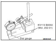
9. Raise the gauge extension (without modifying the position of the magnetic support/gauge assembly), then slide in the tappet to be measured.
• Note dimension (Y) and repeat the operation for the tappets where the valve clearance is not within tolerance.
• Refer to the Replacement Parts Catalogue for the vehicle concerned to select the various thicknesses of the tappet(s).
10. Check the valve clearance again.
11. Remove the camshaft brackets.
12. Remove the camshaft.
13. Remove the tappet(s) not within tolerance.
14. Grease the underside of the tappets and the camshaft brackets.
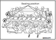
15. Degrease the gasket faces (of the cylinder head and brackets 1 and 6). They should be clean, dry and free from grease (in particular, remove finger marks).
16. Lay four beads of Loctite with a width of 1 mm (0.04 in) on brackets 1 and 6 of the cylinder head.
17. Install the camshaft.
18. Install the camshaft brackets (these are numbered from 1 to 6 and bearing (1) should be positioned on the flywheel end).
: 11 N·m (1.1 kg-m, 8 ft-lb)
 Basic inspection
...
 Symptom diagnosis
Noise, vibration and harshnesS (NVH) Troubleshooting
NVH Troubleshooting - Engine Noise
Use the Chart Below to Help You Find the Cause
of the Symptom
1. Locate the area where noise occurs.
2. C ...
Other materials:
Headlamp aiming switch
Exploded View
1. Headlamp aiming switch
2. Instrument lower panel assembly LH
: Pawl
Removal and Installation
REMOVAL
1. Remove instrment lower panel (LH/RH). Refer to IP-13, "Removal and
Installation".
2. Remove headlamp aiming switch fixing clips, and then remove headlamp aim ...
System
ENGINE CONTROL SYSTEM : System Diagram
1. Priming pump
2. Fuel filter
3. High pressure supply pump
4. High pressure supply pump (internal
transfer pump)
5. High pressure supply pump (volumetric
control valve)
6. High pressure supply pump (high
pressure pump)
7. High pressure supply pum ...
Front drive shaft boot
Exploded View
1. Circular clip
2. Dust shield
3. Housing assembly
4. Boot band
5. Boot
6. Damper band
7. Dynamic damper
8. Circular clip
9. Joint sub-assembly
: Wheel side
: Fill NISSAN Genuine grease or
equivalent.
: Always replace after every
disassembly.
RIGHT SIDE
1. ...
