Nissan Juke Service and Repair Manual : Wiring diagram
WARNING CHIME SYSTEM
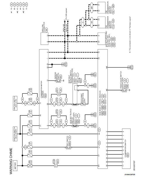
Wiring Diagram
For connector terminal arrangements, harness layouts, and alphabets in a
 (option abbreviation; if not
described in wiring diagram), refer to GI-12, "Connector Information/Explanation
of Option Abbreviation".
 BCM (body control module)
List of ECU Reference
...
 Basic inspection
DIAGNOSIS AND REPAIR WORKFLOW
Work Flow
OVERALL SEQUENCE
DETAILED FLOW
1.OBTAIN INFORMATION ABOUT SYMPTOM
Interview the customer to obtain as much information as possible about the
conditions ...
Other materials:
Front door lock
Exploded View
1. Door key cylinder assembly (driver
side)
Outside handle escutcheon (passenger
side)
2. Outside handle
3. Front gasket
4. Inside handle
5. TORX bolt
6. Door lock assembly
7. Key rod (driver side)
8. Outside handle bracket
9. Rear gasket
10. Key rod protector (driv ...
C1110, C1170 ABS actuator and electric unit (control unit)
DTC Logic
DTC DETECTION LO
DTC CONFIRMATION PROCEDURE
1.PRECONDITIONING
If “DTC CONFIRMATION PROCEDURE” has been previously conducted, always turn
ignition switch OFF and
wait at least 10 seconds before conducting the next test.
>> GO TO 2.
2.CHECK DTC DETECTION
With CONSUL ...
C1121, C1123, C1125, C1127 ABS out valve system
DTC Logic
DTC DETECTION LOGIC
DTC CONFIRMATION PROCEDURE
1.PRECONDITIONING
If “DTC CONFIRMATION PROCEDURE” has been previously conducted, always turn
ignition switch OFF and
wait at least 10 seconds before conducting the next test.
>> GO TO 2.
2.CHECK DTC DETECTION
With CON ...
