Nissan Juke Service and Repair Manual : System
Interior room lamp control system
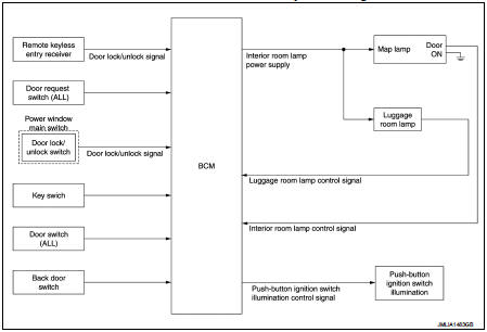
INTERIOR ROOM LAMP CONTROL SYSTEM : System Diagram
INTERIOR ROOM LAMP CONTROL SYSTEM : System Description
OUTLINE
• Interior room lamps* are controlled by interior room lamp timer control function of BCM.
*: Map lamp (when map lamp switch is in DOOR position).
• Luggage room lamp is controlled by luggage room lamp control function of BCM.
• Push-button ignition switch illumination is controlled by the push-button ignition switch illumination control function of BCM.(With Intelligent Key)
INTERIOR ROOM LAMP TIMER CONTROL
Interior Room Lamp Timer Basic Operation
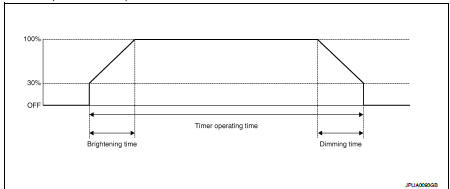
• The interior room lamp turns ON and OFF (gradual brightening and dimming) by the interior room lamp timer.
• BCM judges the vehicle condition with the following items. It activates the interior room lamp timer.
- Ignition switch status*1
- Door switch signal (except back door)
- Door lock/unlock signal (Remote keyless entry receiver, each door request
switch*1, door lock and unlock
switch)
- Key switch signal*2
*1:With Intelligent Key *2:Without Intelligent Key
NOTE
:
Each function of interior room lamp timer can be set by CONSULT-III. Refer to
INL-12, "INT LAMP : CONSULT-
III Function (BCM - INT LAMP)".
Interior Room Lamp ON Operation • BCM always turns the interior room lamp ON when any door opens except back door.
• BCM activates the interior room lamp timer in any of the following conditions to turn the interior room lamp ON for a period of time.
- Status of all doors except back door changes from open to close - Ignition switch is turned ON → OFF - Door unlock signal is detected when all doors close except back door with ignition switch OFF
NOTE
:
The timer restarts if new condition is input during the timer operating time.
Interior Room Lamp OFF Operation BCM stops the timer in any of the following conditions to turn the interior room lamp OFF.
• The timer operating time is expired • Ignition switch is turned OFF → ACC/ON • Door lock signal is detected with all doors close except back door.
LUGGAGE ROOM LAMP CONTROL
BCM turns luggage room lamp ON when the following condition is detected.
• Back door switch is ON BCM turns luggage room lamp OFF when the following condition is detected.
• Back door switch is OFF
PUSH-BUTTON IGNITION SWITCH ILLUMINATION CONTROL (WITH INTELLIGENT KEY)
Push-button Ignition Switch Illumination Basic Operation BCM provides the power supply to turn the push-button ignition switch illumination ON.
Push-button Ignition Switch Illumination ON Operation BCM turns the push-button ignition switch illumination ON in the following conditions.
• Ignition switch ON
• Any of the following conditions with ignition switch OFF/ACC
- Engine start permission is entered
- Driver side door is LOCK → UNLOCK
- Driver side door is open
Push-button Ignition Switch Illumination OFF Operation BCM turns the push-button ignition switch illumination OFF in any of the following conditions.
• The push-button ignition switch illumination ON conditions do not satisfy.
• Any of the following conditions with ignition switch OFF.
- The push-button ignition switch illumination ON conditions do not change (15
seconds after the ignition
switch OFF)
- Driver side door is UNLOCK → LOCK
Interior room lamp battery saver system
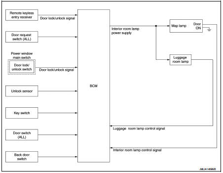
INTERIOR ROOM LAMP BATTERY SAVER SYSTEM : System Diagram
INTERIOR ROOM LAMP BATTERY SAVER SYSTEM : System Description
OUTLINE
• Interior room lamp battery saver is controlled by BCM.
• BCM turns applicable lamps OFF depending on the vehicle condition. This function prevents the battery from over-discharging if the driver neglects turning OFF the lamps.
Applicable lamps
• Map lamp
• Luggage room lamp
INTERIOR ROOM LAMP BATTERY SAVER FUNCTION
• When the ignition switch is turned to other position than ON, BCM operates the timer for a period of time to cut the interior room lamp power supply.
• BCM restarts the timer when any of the following signals changes while operating the timer.
- Ignition switch status*1
- Key switch status*2
- Door switch signal (ALL)
- Door lock/unlock signal (remote keyless entry receiver, each door request
switch*1, door lock and unlock
switch, unlock sensor)
• BCM provides the interior room lamp power supply continuously when the ignition switch position is ON.
*1:With Intelligent Key
*2:Without Intelligent Key
NOTE
:
Each function of interior room lamp battery saver can be set by CONSULT-III.
Refer to INL-13, "BATTERY
SAVER : CONSULT-III Function (BCM - BATTERY SAVER)".
Illumination control system
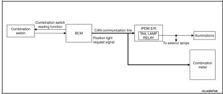
ILLUMINATION CONTROL SYSTEM : System Diagram
ILLUMINATION CONTROL SYSTEM : System Description
OUTLINE
Each illumination lamp is controlled by each function of BCM and IPDM E/R.
Control by BCM
• Combination switch reading function
• Headlamp control function
Control by IPDM E/R
• Relay control function
Control by combination meter • Meter illumination control function (Refer to MWI-11, "SPEEDOMETER : System Description".)
ILLUMINATION CONTROL
• BCM detects the combination switch condition by the combination switch reading function.
• BCM transmits position light request signal to IPDM E/R and combination meter according to tail lamp ON condition.
Tail lamp ON condition
- Lighting switch 1ST
- Lighting switch 2ND
- Lighting switch AUTO, and the auto light function ON judgment (With auto light
system)
• IPDM E/R turns the integrated tail lamp relay ON according to position light request signal. It provides the power supply to each illumination lamp.
• Combination meter enters in the nighttime mode according to position light request signal. Under the nighttime mode the combination meter controls the illuminance by controlling the each illumination lamp (ground side).
 Component parts
INTERIOR LIGHTING SYSTEM
INTERIOR LIGHTING SYSTEM : Component Parts Location
1. IPDM E/R
Refer to PCS-5, "Component Parts
Location"
2. BCM
Refer to BCS-6, "BODY CONTROL
SYSTEM ...
 Diagnosis system (BCM) (with intelligent key system)
Common item
COMMON ITEM : CONSULT-III Function (BCM - COMMON ITEM)
APPLICATION ITEM
CONSULT-III performs the following functions via CAN communication with BCM.
SYSTEM APPLICATION
BCM can perfo ...
Other materials:
Front wheel hub and knuckle
Exploded View
1. Steering knuckle
2. Splash guard
3. Hub bolt
4. Wheel hub assembly (Bearing-integrated
type)
5. Disc rotor
6. Wheel hub lock nut
7. Adjusting cap
8. Cotter pin
A. Tightening must be done following the installation procedure. Refer to
FAX-43, "Removal and Insta ...
P0201, P0202, P0203, P0204 fuel injector
DTC Logic
DTC DETECTION LOGIC
DTC CONFIRMATION PROCEDURE
1.PRECONDITIONING
If DTC Confirmation Procedure has been previously conducted, always perform
the following procedure
before conducting the next test.
1. Turn ignition switch OFF and wait at least 10 seconds.
2. Turn ignition swit ...
Chassis control
The chassis control module is a sophisticated electronic system integrated into the Nissan Leaf designed to enhance both vehicle stability and occupant comfort through the following primary functions:
Intelligent Trace Control (I-TC)
Active Ride Control (ARC)
Intel ...
