Nissan Juke Service and Repair Manual : Front wiper auto stop signal circuit
Component Function Check
1.CHECK FRONT WIPER (AUTO STOP) SIGNAL
 CONSULT-III DATA MONITOR
1. Select “WIP AUTO STOP” of IPDM E/R data monitor item.
2. Operate the front wiper.
3. With the front wiper operation, check the monitor status.
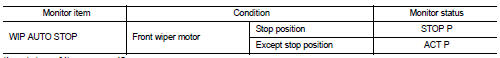
Is the status of item normal? YES >> Auto stop signal circuit is normal.
NO >> Refer to WW-40, "Diagnosis Procedure".
Diagnosis Procedure
1.CHECK IPDM E/R OUTPUT VOLTAGE
1. Turn ignition switch OFF.
2. Disconnect front wiper motor connector.
3. Turn ignition switch ON.
4. Check voltage between front wiper motor harness connector and ground.
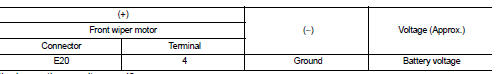
Is the inspection result normal? YES >> Replace front wiper motor.
NO >> GO TO 2.
2.CHECK FRONT WIPER MOTOR (AUTO STOP) CIRCUIT
1. Turn ignition switch OFF.
2. Disconnect IPDM E/R connector.
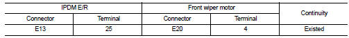
3. Check continuity between IPDM E/R harness connector and front wiper motor harness connector.
4. Check continuity between IPDM E/R harness connector and ground.
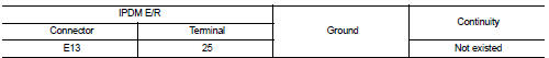
Is the inspection result normal? YES >> Replace IPDM E/R.
NO >> Repair or replace harness.
 Front wiper motor hi circuit
Component Function Check
1.CHECK FRONT WIPER HI OPERATION
CONSULT-III ACTIVE TEST
1. Select “FRONT WIPER” of IPDM E/R active test item.
2. With operating the test item, check front wiper opera ...
 Front wiper motor ground circuit
Diagnosis Procedure
1.CHECK FRONT WIPER MOTOR GROUND CIRCUIT
1. Turn ignition switch OFF.
2. Disconnect front wiper motor connector.
3. Check continuity between front wiper motor harness connector ...
Other materials:
Cooling fan
Component Function Check
1.CHECK COOLING FAN FUNCTION
With CONSULT-III
1. Turn ignition switch ON.
2. Perform “FAN DUTY CONTROL” in “ACTIVE TEST” mode of “ENGINE” using
CONSULT-III.
3. Check that cooling fan speed varies according to the percentage.
Without CONSULT-III
1. Acti ...
Diagnosis system (EPS control unit)
Consult-III Function
FUNCTION
CONSULT-III can display each diagnostic item using the diagnostic test modes
shown following.
*: The following diagnosis information is erased by erasing.
• DTC
• Freeze frame data (FFD)
ECU IDENTIFICATION
Displays the part number stored in the control un ...
P0131 A/F sensor 1
DTC Logic
DTC DETECTION LOGIC
To judge the malfunction, the diagnosis checks that the A/F signal computed
by ECM from the A/F sensor 1
signal is not inordinately low.
DTC CONFIRMATION PROCEDURE
1.PRECONDITIONING
If DTC Confirmation Procedure has been previously conducted, always perform
...
