Nissan Juke Service and Repair Manual : Front wiper motor hi circuit
Component Function Check
1.CHECK FRONT WIPER HI OPERATION
 CONSULT-III ACTIVE TEST
1. Select “FRONT WIPER” of IPDM E/R active test item.
2. With operating the test item, check front wiper operation.
Hi : Front wiper (HI) operation Off : Stop the front wiper
Is front wiper (HI) operation normally? YES >> Front wiper motor HI circuit is normal.
NO >> Refer to WW-39, "Diagnosis Procedure".
Diagnosis Procedure
1.CHECK FRONT WIPER MOTOR (HI) OUTPUT VOLTAGE
 CONSULT-III ACTIVE TEST
1. Turn ignition switch OFF.
2. Disconnect front wiper motor connector.
3. Turn ignition switch ON.
4. Select “FRONT WIPER” of IPDM E/R active test item.
5. With operating the test item, check voltage between front wiper motor harness connector and ground.
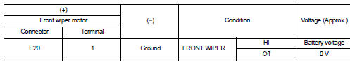
Is the inspection result normal? YES >> Replace front wiper motor.
NO >> GO TO 2.
2.CHECK FRONT WIPER MOTOR (HI) CIRCUIT
1. Turn ignition switch OFF.
2. Disconnect IPDM E/R connector.
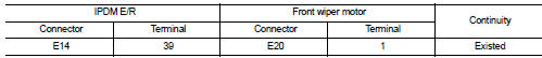
3. Check continuity between IPDM E/R harness connector and front wiper motor harness connector.
4. Check continuity between IPDM E/R harness connector and ground.
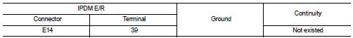
Is the inspection result normal? YES >> Replace IPDM E/R.
NO >> Repair or replace harness.
 Front wiper motor lo circuit
Component Function Check
1.CHECK FRONT WIPER LO OPERATION
CONSULT-III ACTIVE TEST
1. Select “FRONT WIPER” of IPDM E/R active test item.
2. With operating the test item, check front wiper opera ...
 Front wiper auto stop signal circuit
Component Function Check
1.CHECK FRONT WIPER (AUTO STOP) SIGNAL
CONSULT-III DATA MONITOR
1. Select “WIP AUTO STOP” of IPDM E/R data monitor item.
2. Operate the front wiper.
3. With the front ...
Other materials:
P1804, P1809 4WD control module
DTC Logic
DTC DETECTION LOGIC
DTC CONFIRMATION PROCEDURE
1.PRECONDITIONING
If “DTC CONFIRMATION PROCEDURE” has been previously conducted, always turn
ignition switch OFF and
wait at least 10 seconds before conducting the next test.
>> GO TO 2.
2.DTC REPRODUCTION PROCEDURE
W ...
P183A coupling temperature sensor right
DTC Logic
DTC DETECTION LOGIC
DTC CONFIRMATION PROCEDURE
1.PRECONDITIONING
If “DTC CONFIRMATION PROCEDURE” has been previously conducted, always turn
ignition switch OFF and
wait at least 10 seconds before conducting the next test.
>> GO TO 2.
2.DTC REPRODUCTION PROCEDURE
W ...
Does not operate
Description
ABS function and EBD function does not operate.
Diagnosis Procedure
CAUTION:
ABS function and EBD function never operate when the vehicle speed is 10 km/h
(6.2 MPH) or less.
1.CHECK ABS WARNING LAMP
Check that ABS warning lamp and brake warning lamp turn ON and turn OFF
appro ...
