Nissan Juke Service and Repair Manual : Thermo plunger unit
Exploded View
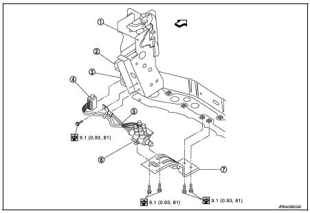
1. Side member LH
2. Thermo plunger control unit
3. Thermo plunger relay
4. Thermo plunger connector
5. Earth lead
6. Thermo plunger unit
7. Bracket stay
 Vehicle front
 : N·m (kg-m, in-lb)
Removal and Installation
REMOVAL
1. Remove battery cable from the negative terminal.
2. Drain engine coolant. Refer to CO-62, "Draining".
3. Remove the fender protector (LH). Refer to EXT-22, "Exploded View".
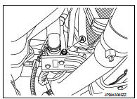
4. Disconnect thermo plunger connector.
5. Remove the earth lead nut (A
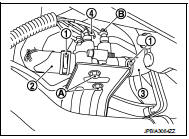
6. Remove the thermo plunger connection caps (4).
7. Remove the thermo plunger connection nuts (B) using the appropriate tool.
8. Remove the LH and RH clamps (1) and hoses (2) and (3).
9. Remove the fixing bolts (A) of the thermo plunger from the bracket and remove the thermo plunger unit.
Tightening torque of bolt : 9.1 N.m
INSTALLATION
Installation is basically the reverse order of the removal.
 Water pump
Exploded View
1. Water pump
2. Gasket
3. Cylinder block
Removal and Installation
WARNING:
Never remove the radiator cap when the engine is hot. Serious burns could occur
from high pressure ...
 Thermostat
Inspection
• Place a thread so that it is caught in the valves of the thermostat.
Immerse fully in a container filled with water. Heat while stirring.
(The example in the figure shows the the ...
Other materials:
High pressure fuel pump
Component Function Check
1.CHECK HIGH PRESSURE FUEL PUMP FUNCTION
With CONSULT-III
1. Start engine.
2. Check “FUEL PRES SEN V” in “DATA MONITOR” mode of “ENGINE” using CONSULT-III.
Without CONSULT-III
1. Start engine.
2. Check the voltage between ECM harness connector terminals ...
P1226 TP sensor
DTC Logic
DTC DETECTION LOGIC
DTC CONFIRMATION PROCEDURE
1.PRECONDITIONING
If DTC Confirmation Procedure has been previously conducted, always turn
ignition switch OFF and wait at
least 10 seconds before conducting the next test.
TESTING CONDITION:
Before performing the following proced ...
Cooler pipe and hose
Exploded View
1. A/C unit assembly
2. O-ring
3. High-pressure pipe
4. O-ring
5. Low-pressure flexible hose
6. High-pressure flexible hose
7. O-ring
8. Condenser
9. Compressor
: Do not reuse
: N·m (kg-m, in-lb)
: N·m (kg-m, ft-lb)
High-pressure flexible hose : Removal and Instal ...
