Nissan Juke Service and Repair Manual : Fuel pressure
Work Procedure
FUEL PRESSURE RELEASE
 With CONSULT-III
1. Turn ignition switch ON.
2. Perform ŌĆ£FUEL PRESSURE RELEASEŌĆØ in ŌĆ£WORK SUPPORTŌĆØ mode of ŌĆ£ENGINEŌĆØ using CONSULT-III.
3. Start engine.
4. After engine stalls, crank it two or three times to release all fuel pressure.
5. Turn ignition switch OFF.
 Without CONSULT-III
1. Remove fuel pump fuse located in IPDM E/R.
2. Start engine.
3. After engine stalls, crank it two or three times to release all fuel pressure.
4. Turn ignition switch OFF.
5. Reinstall fuel pump fuse after servicing fuel system.
FUEL PRESSURE CHECK
CAUTION:
ŌĆó Before disconnecting fuel line, release fuel pressure from fuel line to
eliminate danger.
ŌĆó The fuel hose connection method used when taking fuel pressure check must not be used for other purposes.
ŌĆó Be careful not to scratch or put debris around connection area when servicing, so that the quick connector maintains sealability with O-rings inside.
ŌĆó Do not perform fuel pressure check with electrical systems operating (i.e. lights, rear defogger, A/C, etc.) Fuel pressure gauge may indicate false readings due to varying engine load and changes in manifold vacuum.
NOTE:
Prepare pans or saucers under the disconnected fuel line because the fuel may spill out. The fuel pressure cannot be completely released because J10 models do not have fuel return system.
1. Release fuel pressure to zero.
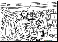
2. Prepare fuel hose for fuel pressure check B and fuel tube adapter [SST: KV10118400] D, then connect fuel pressure gauge A.
ŌĆó  : To quick connector
ŌĆó  : To fuel tube (engine side)
ŌĆó C: Clamp
ŌĆó Use suitable fuel hose for fuel pressure check (genuine NISSAN
fuel hose without quick connector).
ŌĆó To avoid unnecessary force or tension to hose, use moderately long fuel hose for fuel pressure check.
ŌĆó Do not use the fuel hose for checking fuel pressure with damage or cracks on it.
ŌĆó Use Pressure Gauge to check fuel pressure.
3. Remove fuel hose.
ŌĆó Do not twist or kink fuel hose because it is plastic hose.
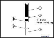
4. Connect fuel hose for fuel pressure check (1) to fuel tube (engine side) with clamp (2) as shown in the figure.
ŌĆó No.2 spool (5)
ŌĆó Wipe off oil or dirt from hose insertion part using cloth moistened
with gasoline.
ŌĆó Apply proper amount of gasoline between top of the fuel tube (3) and No.1 spool (4).
ŌĆó Insert fuel hose for fuel pressure check until it touches the No.1 spool on fuel tube.
ŌĆó Use NISSAN genuine hose clamp (part number: 16439 N4710 or 16439 40U00).
ŌĆó When reconnecting fuel line, always use new clamps.
ŌĆó Use a torque driver to tighten clamps.
ŌĆó Install hose clamp to the position within 1 - 2 mm (0.04 - 0.08 in).
Tightening torque: 1 - 1.5 N┬Ęm (0.1 - 0.15 kg-m, 9 - 13 in-lb)
ŌĆó Make sure that clamp screw does not contact adjacent parts.
5. Connect fuel tube adapter to quick connector.
ŌĆó A: Fuel pressure gauge ŌĆó B: Fuel hose for fuel pressure check 6. After connecting fuel hose for fuel pressure check, pull the hose with a force of approximately 98 N (10 kg, 22 lb) to confirm fuel tube does not come off.
7. Turn ignition switch ON and check for fuel leakage.
8. Start engine and check for fuel leakage.
9. Read the indication of fuel pressure gauge.
ŌĆó Do not perform fuel pressure check with system operating.
Fuel pressure gauge may indicate false readings.
ŌĆó During fuel pressure check, confirm for fuel leakage from fuel connection every 3 minutes.
At idling: Approximately 350 kPa (3.5 bar, 3.57 kg/cm2, 51 psi)
10. If result is unsatisfactory, go to next step.
11. Check the following.
ŌĆó Fuel hoses and fuel tubes for clogging
ŌĆó Fuel filter for clogging
ŌĆó Fuel pump
ŌĆó Fuel pressure regulator for clogging
If OK, replace fuel pressure regulator.
If NG, repair or replace.
 Mixture ratio self-learning value
clear
Mixture ratio self-learning value
clear
Description
This describes how to erase the mixture ratio self-learning value. For the
actual procedure, follow the instructions
in ŌĆ£Diagnosis ProcedureŌĆØ.
Work Procedure
With CONSULT-III
1. ...
 How to set srt code
Description
OUTLINE
In order to set all SRTs, the self-diagnoses as in the ŌĆ£SRT ITEMŌĆØ table must
have been performed at least
once. Each diagnosis may require actual driving for a long period ...
Other materials:
Tire pressure
Tire Pressure Monitoring System (TPMS) This vehicle is equipped with the Tire
Pressure Monitoring System (TPMS). It monitors tire pressure of all tires except
the spare. When the low tire pressure warning light is lit, and the CHECK TIRE PRES
(pressure) warning message is displayed in the vehi ...
The parking brake release warning continues sounding, or
does not sound
Description
ŌĆó The parking brake warning buzzer sounds continuously during vehicle travel
though the parking brake is
released.
ŌĆó The parking brake warning buzzer does not sound at all even though driving the
vehicle with the parking
brake applied.
Diagnosis Procedure
1.CHECK PARKING BR ...
Tire Pressure Monitoring System (TPMS)
Your Nissan Leaf is equipped with a sophisticated Tire Pressure Monitoring System (TPMS) that continuously tracks the inflation pressure of all four tires. When the dedicated low tire pressure warning light illuminates on the instrument cluster, accompanied by the "Tire Pressure Low - Add Air" notif ...
