Nissan Juke Service and Repair Manual : Transverse link
Exploded View
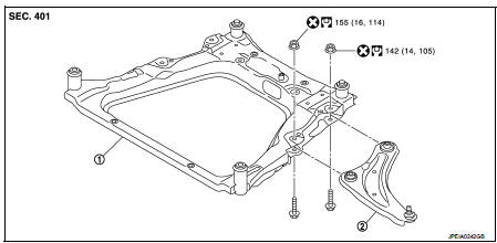
1. Front suspension member 2. Transverse link
 : Always replace after every
disassembly.
 : N·m (kg-m, ft-lb)
Removal and Installation
REMOVAL
1. Remove tires. Refer to WT-7, "Removal and Installation".
2. Remove transverse link from steering knuckle.
• MR16DDT: Refer to FAX-11, "Removal and Installation".
• HR16DE: Refer to FAX-43, "Removal and Installation".
• K9K: Refer to FAX-68, "Removal and Installation".
3. Remove transverse link from suspension member.
INSTALLATION
Note the following, and install in the reverse order of removal.
• Never reuse transverse link mounting nut.
• Perform final tightening of bolts and nuts at the vehicle installation position (rubber bushing), under unladen conditions with tires on level ground.
• Perform inspection after installation. Refer to FSU-14, "Inspection".
Inspection
INSPECTION AFTER REMOVAL
Check the following items, and replace the parts if necessary.
Transverse Link
• Transverse link and bushing for deformation, cracks or damage.
• Ball joint boot for cracks or other damage, and also for grease leakage.
Swing Torque
1. Manually move ball stud to confirm it moves smoothly with no binding.
2. Move ball stud at least ten times by hand to check for smooth movement.
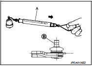
3. Hook a spring balance (A) at cutout on ball stud (B). Confirm spring balance measurement value is within specifications when ball stud begins moving.
Swing torque : Refer to FSU-22, "Ball Joint".
Measurement on spring balance : Refer to FSU-22, "Ball Joint"
• If swing torque exceeds standard range, replace transverse link assembly.
Axial End Play
1. Move ball stud at least ten times by hand to check for smooth movement.
2. Move tip of ball stud in axial direction to check for looseness.
Axial end play : Refer to FSU-22, "Ball Joint".
• If axial end play exceeds the standard value, replace transverse link assembly.
INSPECTION AFTER INSTALLATION
Check wheel alignment. Refer to FSU-7, "Inspection".
 Front coil spring and strut
Exploded View
2WD
1. Piston rod lock nut
2. Mounting insulator
3. Mounting bearing
4. Bound bumper
5. Coil spring
6. Lower rubber seat
7. Strut
8. Steering knuckle
: N·m (kg-m, ft-lb ...
 Front stabilizer
Exploded View
1. Stabilizer bar
2. Stabilizer clamp
3. Stabilizer bushing
4. Stabilizer connecting rod
5. Strut assembly
6. Front suspension member
: N·m (kg-m, ft-lb)
Removal and Insta ...
Other materials:
U1000 can comm circuit
Description
CAN (Controller Area Network) is a serial communication line for real time
applications. It is an on-vehicle multiplex
communication line with high data communication speed and excellent error
detection ability. Modern
vehicle is equipped with many electronic control unit, and eac ...
General Precautions
WARNING:
When replacing fuel line parts, be sure to observe the following.
• Put a “CAUTION: FLAMMABLE” sign in the workshop.
• Be sure to work in a well ventilated area and furnish workshop with a CO2 fire
extinguisher.
• Never smoke while servicing fuel system. Keep open flames a ...
B2614 ACC relay circuit
DTC Logic
DTC DETECTION LOGIC
DTC CONFIRMATION PROCEDURE
1.PERFORM DTC CONFIRMATION PROCEDURE
1. Turn the power supply position to ACC under the following conditions, and
wait for 2 second or more.
CVT models
- Selector lever is in the P or N position
- Do not depress brake pedal
M/T m ...
