Nissan Juke Service and Repair Manual : Evaporative emission system
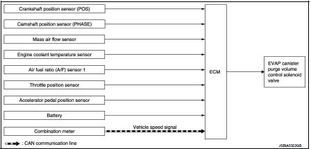
Evaporative emission system: System Diagram
Evaporative emission system : System Description
INPUT/OUTPUT SIGNAL CHART
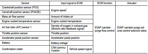
*: ECM determines the start signal status by the signals of engine speed and battery voltage.
SYSTEM DESCRIPTION
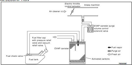
The evaporative emission system is used to reduce hydrocarbons emitted into the atmosphere from the fuel system. This reduction of hydrocarbons is accomplished by activated charcoals in the EVAP canister.
The fuel vapor in the sealed fuel tank is led into the EVAP canister which contains activated carbon and the vapor is stored there when the engine is not operating or when refueling to the fuel tank.
The vapor in the EVAP canister is purged by the air through the purge line to the intake manifold when the engine is operating. EVAP canister purge volume control solenoid valve is controlled by ECM. When the engine operates, the flow rate of vapor controlled by EVAP canister purge volume control solenoid valve is proportionally regulated as the air flow increases.
EVAP canister purge volume control solenoid valve also shuts off the vapor purge line during decelerating and idling.
 Starter motor drive control
Starter motor drive control : System Diagram
Starter motor drive control : System
DescriptionINPUT/OUTPUT SIGNAL CHART
INPUT/OUTPUT SIGNAL CHART
*: With Intelligent Key system
SYSTEM DESCRIPT ...
 Automatic speed control device (ASCD)
Automatic speed control device (ASCD)
: System Diagram
Automatic speed control device (ASCD)
: System Description
INPUT/OUTPUT SIGNAL CHART
*1: M/T models
*2: CVT models
BASIC ASCD SYSTEM
...
Other materials:
NISSAN dynamic control system
NISSAN dynamic control system : System
Diagram
CVT models
M/T models
NISSAN dynamic control system : System
Description
CVT models
System Description
TCM transmits a drive mode select signal to ECM via CAN communication, according
to a NORMAL mode
signal, SPORT mode signal, or ECO mo ...
C1176 stop lamp SW2
DTC Logic
DTC DETECTION LOGIC
DTC CONFIRMATION PROCEDURE
1.PRECONDITIONING
If “DTC CONFIRMATION PROCEDURE” has been previously conducted, always turn
ignition switch OFF and
wait at least 10 seconds before conducting the next test.
>> GO TO 2.
2.CHECK DTC DETECTION
With CON ...
Parking brake
WARNING
Be absolutely sure that the mechanical or electronic parking brake is completely released before driving your vehicle. Failure to do so could cause rapid brake overheating, subsequent friction brake failure, and lead to a serious accident.
Do not attempt to release th ...
