Nissan Juke Service and Repair Manual : Starter motor drive control
Starter motor drive control : System Diagram
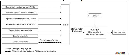
Starter motor drive control : System DescriptionINPUT/OUTPUT SIGNAL CHART
INPUT/OUTPUT SIGNAL CHART
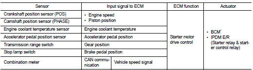
*: With Intelligent Key system SYSTEM DESCRIPTION
When rapid deceleration occurs during engine runs or idle speed decreases due
to heavy load conditions,
ECM detects a decrease in idle speed and restarts the engine to secure
reliability in handleability by transmitting
a cranking request signal to IPDM E/R for activating the starter motor under the
following conditions:
• Selector lever: P or any position other than N
• Idle switch: ON (Accelerator pedal not depressed)
• Brake switch: ON (Brake pedal depressed)
Models with no Intelligent Key System transmit a control signal directly to IPDM E/R. On the other hand, models with the Intelligent Key System transmit a control signal to IPDM E/R by way of BCM via CAN communication.
IPDM E/R detects an operating state of the starter motor relay and the starter motor control relay and transmits a feed back signal to ECM via CAN Communication.
 Cooling fan control
Cooling fan control : System Diagram
Cooling fan control : System Description
INPUT/OUTPUT SIGNAL CHART
*: The ECM determines the start signal status by the signals of engine speed
and batter ...
 Evaporative emission system
Evaporative emission system: System
Diagram
Evaporative emission system : System
Description
INPUT/OUTPUT SIGNAL CHART
*: ECM determines the start signal status by the signals of engine spee ...
Other materials:
Precaution Necessary for Steering Wheel Rotation after Battery Dis
NOTE:
• Before removing and installing any control units, first turn the ignition
switch to the LOCK position, then disconnect
both battery cables.
• After finishing work, confirm that all control unit connectors are connected
properly, then re-connect both
battery cables.
• Always us ...
B26F7 BCM
DTC Logic
DTC DETECTION LOGIC
DTC CONFIRMATION PROCEDURE
1.PERFORM DTC CONFIRMATION PROCEDURE
1. Press door request switch.
2. Turn ignition switch ON.
3. Check DTC in “Self Diagnostic Result” mode of “BCM” using CONSULT-III.
Is DTC detected?
YES >> Go to SEC-127, "Dia ...
Front door
Exploded View
1. Front door panel
2. Grommet
3. TORX bolt
4. Door striker
5. Door pad
6. Bumper rubber
7. Door check link
8. Door hinge (lower)
9. Door hinge (upper)
10. Grommet
: Do not reuse
: N·m (kg-m, in-lb)
: N·m (kg-m, ft-lb)
: Body grease
Door assembly
DOOR ASSEMBLY ...
