Nissan Juke Service and Repair Manual : Cooling fan control
Cooling fan control : System Diagram
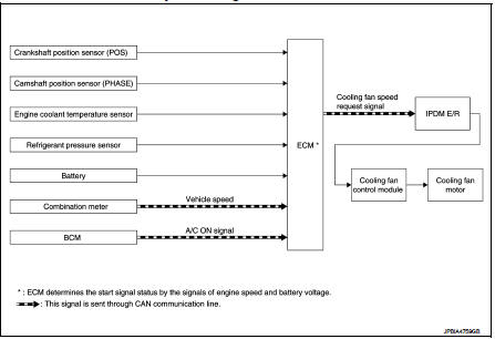
Cooling fan control : System Description
INPUT/OUTPUT SIGNAL CHART
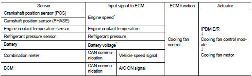
*: The ECM determines the start signal status by the signals of engine speed and battery voltage.
SYSTEM DESCRIPTION
ECM controls cooling fan speed corresponding to vehicle speed, engine coolant temperature, A/C ON signal and refrigerant pressure.
Cooling fan control signal is sent to IPDM E/R from ECM by CAN communication line. Then, IPDM E/R sends ON/OFF pulse duty signal to cooling fan control module. Corresponding to this ON/OFF pulse duty signal, cooling fan control module gives cooling fan motor operating voltage to cooling fan motors. Cooling fan speed is controlled by duty cycle of cooling fan motor operating voltage sent from cooling fan control module.
 Air conditioning cut control
Air conditioning cut control : System Diagram
Air conditioning cut control : System Description
INPUT/OUTPUT SIGNAL CHART
*: ECM determines the start signal status by the signals of engine spe ...
 Starter motor drive control
Starter motor drive control : System Diagram
Starter motor drive control : System
DescriptionINPUT/OUTPUT SIGNAL CHART
INPUT/OUTPUT SIGNAL CHART
*: With Intelligent Key system
SYSTEM DESCRIPT ...
Other materials:
Key switch
Component Function Check
1.CHECK FUNCTION
1. Select ÔÇťDOOR LOCKÔÇŁ of ÔÇťBCMÔÇŁ using CONSULT-III.
2. Select ÔÇťKEY ON SWÔÇŁ in ÔÇťDATA MONITORÔÇŁ mode.
3. Check that the function operates normally according to the following
conditions.
Is the inspection result normal?
YES >> Key sw ...
P0603 ECM
Description
ECM has the memory function of the DTC memory, the air-fuel ratio
feedback compensation value memory, the Idle Air Volume Learning
value memory, etc. even when the ignition switch is turned OFF.
DTC Logic
DTC DETECTION LOGIC
*: This self-diagnosis is not for ECM power supply ci ...
Unbalance steering wheel turning force and return between
right and left
Description
Unbalance steering wheel turning force and return between right and left.
Diagnosis Procedure
1.CHECK THE ILLUMINATION OF THE EPS WARNING LAMP
Check the EPS warning lamp while engine is running.
Does the EPS warning lamp turn OFF?
YES >> GO TO 2.
NO >> Refer to STC ...
