Nissan Juke Service and Repair Manual : Air conditioning cut control
Air conditioning cut control : System Diagram
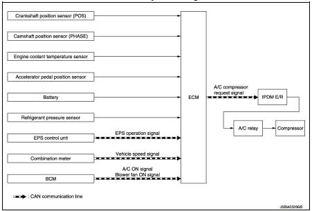
Air conditioning cut control : System Description
INPUT/OUTPUT SIGNAL CHART
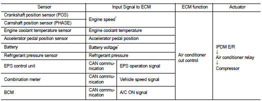
*: ECM determines the start signal status by the signals of engine speed and battery voltage.
SYSTEM DESCRIPTION
This system improves engine operation when the air conditioner is used.
Under the following conditions, the air conditioner is turned off.
ŌĆó When the accelerator pedal is fully depressed.
ŌĆó When cranking the engine.
ŌĆó At high engine speeds.
ŌĆó When the engine coolant temperature becomes excessively high.
ŌĆó When operating power steering during low engine speed or low vehicle speed.
ŌĆó When engine speed is excessively low.
ŌĆó When refrigerant pressure is excessively low or high.
 Engine protection control at low engine oil pressure
Engine protection control at low engine oil pressure : System Diagram
Engine protection control at low engine oil pressure : System Description
INPUT/OUTPUT SIGNAL CHART
SYSTEM DESCRIPTION
ŌĆ ...
 Cooling fan control
Cooling fan control : System Diagram
Cooling fan control : System Description
INPUT/OUTPUT SIGNAL CHART
*: The ECM determines the start signal status by the signals of engine speed
and batter ...
Other materials:
Meters and indicators
Your Nissan Leaf provides specialized real-time data through various meters and gauges, all conveniently accessible via the primary vehicle information display.
Meter
Master warning light
The master warning light (available in red or yellow) illuminates on the in ...
B1182 lap Pre-tensioner LH
DTC Logic
DTC CONFIRMATION PROCEDURE
1.CHECK SELF-DIAGNOSTIC RESULT
With CONSULT-III
1. Turn ignition switch ON.
2. Perform ŌĆ£Self Diagnostic ResultŌĆØ mode of ŌĆ£AIR BAGŌĆØ using CONSULT-III.
Without CONSULT-III
1. Turn ignition switch ON.
2. Check the air bag warning lamp status. Refe ...
Rear window defogger system
Wiring Diagram - DEFOGGER CONTROL SYSTEM -
For connector terminal arrangements, harness layouts, and alphabets in a
(option abbreviation; if not
described in wiring diagram), refer to GI-12, "Connector Information/Explanation
of Option Abbreviation".
...
