Nissan Juke Service and Repair Manual : Wiring diagram
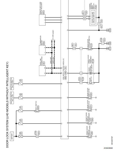
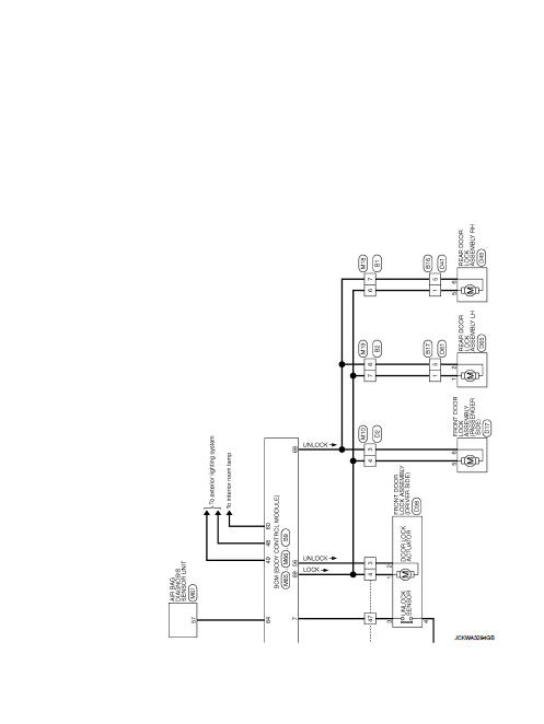
DOOR & LOCK SYSTEM
Wiring Diagram
For connector terminal arrangements, harness layouts, and alphabets in a
 (option abbreviation; if not
described in wiring diagram), refer to GI-12, "Connector Information/Explanation
of Option Abbreviation".
 ECU diagnosis information
BCM
List of ECU Reference
...
 Basic inspection
...
Other materials:
Precaution Necessary for Steering Wheel Rotation after Battery Disconnect
NOTE:
• Before removing and installing any control units, first turn the ignition
switch to the LOCK position, then disconnect
both battery cables.
• After finishing work, confirm that all control unit connectors are connected
properly, then re-connect both
battery cables.
• Always us ...
Conventional (fixed speed) cruise control mode
The conventional (fixed speed) cruise control mode in your Nissan Leaf offers a traditional driving experience, allowing you to maintain a constant speed between 25 and 90 mph (40 to 144 km/h) without the need to keep your foot engaged on the accelerator pedal.
WARNING
Unlike the ...
Door does not lock/unlock with door request switch
All door request switches
ALL DOOR REQUEST SWITCHES : Description
All doors do not lock/unlock using all door request switches.
ALL DOOR REQUEST SWITCHES : Diagnosis Procedure
1.CHECK REMOTE KEYLESS ENTRY FUNCTION
Check remote keyless entry function.
Does door lock/unlock with Intelligent Ke ...
