Nissan Juke Service and Repair Manual : Back door opener actuator
Component Function Check
1.CHECK FUNCTION
1. Select ÔÇťINTELLIGENT KEYÔÇŁ of ÔÇťBCMÔÇŁ using CONSULT-III.
2. Select ÔÇťTRUNK/BACK DOORÔÇŁ in ÔÇťACTIVE TESTÔÇŁ mode.
3. Check that the function operates normally according to the following conditions.

Is the inspection result normal? YES >> Back door opener actuator is OK.
NO >> Refer to DLK-67, "Diagnosis Procedure".
Diagnosis Procedure
1.CHECK BACK DOOR OPENER ACTUATOR INPUT SIGNAL
1. Turn ignition switch OFF.
2. Disconnect back door lock assembly connector.
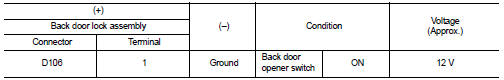
3. Check voltage between back door lock assembly harness connector and ground.
Is the inspection result normal? YES >> GO TO 3.
NO >> GO TO 2.
2.CHECK BACK DOOR OPENER ACTUATOR CIRCUIT
1. Disconnect BCM connector.
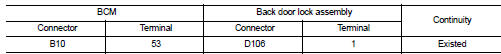
2. Check continuity between BCM harness connector and back door lock assembly harness connector.
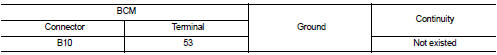
3. Check continuity between BCM harness connector and ground.
Is the inspection result normal? YES >> Replace BCM. Refer to BCS-93, "Removal and Installation".
NO >> Repair or replace harness.
3.CHECK BACK DOOR OPENER ACTUATOR GROUND CIRCUIT
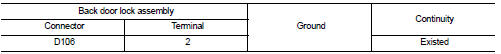
Check continuity between back door lock assembly harness connector and ground.
Is the inspection normal? YES >> Replace back door lock assembly.
NO >> Repair or replace harness.
 B2628 outside antenna
DTC Logic
DTC DETECTION LOGIC
DTC CONFIRMATION PROCEDURE
1.PERFORM DTC CONFIRMATION PROCEDURE
1. Disconnect outside key antenna (rear bumper) connector.
2. Perform ÔÇťINTELLIGENT KEYÔÇŁ Self Di ...
 Back door opener switch
Component Function Check
1.CHECK FUNCTION
1. Select ÔÇťTRUNKÔÇŁ of ÔÇťBCMÔÇŁ using CONSULT-III.
2. Select ÔÇťTR/BD OPEN SWÔÇŁ in ÔÇťDATA MONITORÔÇŁ mode.
3. Check that the function operates normal ...
Other materials:
Clutch pedal
LHD : Exploded View
1. Clutch pedal
2. Stopper rubber
3. Clip
4. Clutch interlock switch *1
5. Clutch pedal position switch *2
6. Pedal pad
7. Pedal stopper rubber
*1 : With push-button ignition switch system
*2 : With ASCD or with push-button ignition switch system
: N┬Ěm (kg-m, ft- ...
Output speed sensor
Exploded View
1. Transaxle assembly
2. Output speed sensor
3. O-ring
: Vehicle front
: Always replace after every
disassembly.
: N┬Ěm (kg-m, in-lb)
: Genuine NISSAN CVT Fluid NS-2
Removal and Installation
REMOVAL
1. Disconnect battery cable from negative terminal. Refer to PG-124, &q ...
Drive belt
1. Alternator
2. Drive belt auto-tensioner
3. Crankshaft pulley
4. Air conditioner compressor
5. Water pump
WARNING
Be sure the ignition switch is in the OFF or LOCK position before servicing
drive belts. The engine could rotate unexpectedly.
1. Visually inspect the belt for signs of unus ...
